Overview

MightyHat is a Raspberry Pi Hat with that makes it easy to build a compact, robust, battery backed-up gateway for the internet of things. It accepts RFM69W/HW/HCW or LoRa transceivers and acts as a power controller and UPS for the RaspberryPi.

Features

  • Atmega328p @ 16mhz, 3.3v interfacing with the Pi via several GPIO: 2 for the power control (similar to ATXRaspi), 2 for serial (TX, RX), and a pin (pin 22 aka GPIO 25) to RST the atmega328p
  • ability to program it via FTDI header (when Pi is off), from the Pi with avrdude (when the Pi is running), and wirelessly through Moteino’s Wireless Programming capability
  • optional Nokia 5110 84x48px backlit monochrome LCD for anything you want to display, the sample sketch will make use of this, see below for link. This is a great LCD alternative to the 2×20 character LCD I’ve been using before, and cheaper/more common too, and with the great u8glib font support, you can fit really long messages on the screen
  • optional battery backup can be hot plugged in any time if you want to have backup power (standard 1 cell Lithium Polymer, 2Ah+ with embedded protection circuitry recommended). It will also run without a battery as long as USB power is present. While a battery is attached, the charging circuit will charge the battery if external USB power is also present. If external power is lost the battery kicks in to keep your Pi running. The included sample sketch has a voltage threshold that once reached will trigger the Pi to shutdown cleanly
  • Fun fact: a 2000mAh battery will run a typical setup like the one below (Pi B+, wifi dongle, MightyHat + active atmega328p + RFM69HW + LCD) for about 3 hours before it will shutdown the Pi when the battery reaches a low voltage threshold:
  • external power is conveniently provided through the usual micro USB or 2.1mm jack
  • included red/green button makes for a nice power button that will control power to the Pi through the GPIO header and a power path that includes a 5V booster (similar to MightyBoost). The power path to the Pi is latched so that regardless if the atmega328p is reset, the power to the Pi is uninterrupted (as long as USB or battery is plugged in). This makes it possible to reprogram the atmega328p at any time, even directly from the Pi as I will show in a future walkthrough
  • allow RFM69W/HW and LoRa RFM95/96 transceivers to a wide range of low power and long range RF applications
  • the Pi GPIO is doubled to the top of the board where you can solder headers to bring it to the side. The included headers will also protrude and make all pins accessible on top of the PCB already
  • buzzer if you want to get creative with beeps/alerts
  • 2 general purpose buttons (R2+) allow controlling the backlight and view message history:
  • SMA footprint allows soldering SMA connectors for more aesthetic/commercial looking antennas if you mind the usual wire monopole antenna
  • compact design brings all essential ports to one side (where USB/ethernet is) while allowing easy access to all secondary ports (HDMI, audio, SD card access, etc)
  • pinout of GPIO port (connector to Pi):
  • Assembly samples:

Assembly preview

Here is a short illustrated assembly step progression for a MightyHat R3. It’s important to do things in order to avoid misalignment of headers or incorrect soldering of the main Pi mating header.

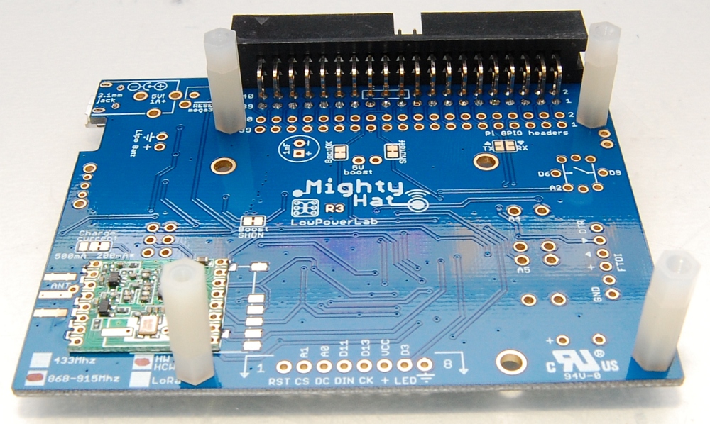
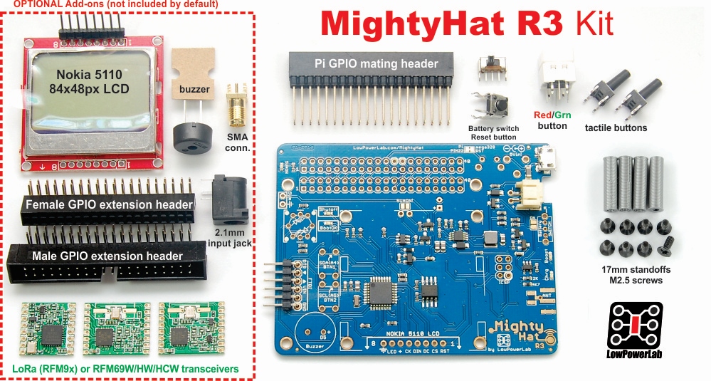
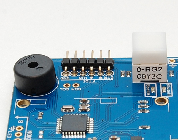
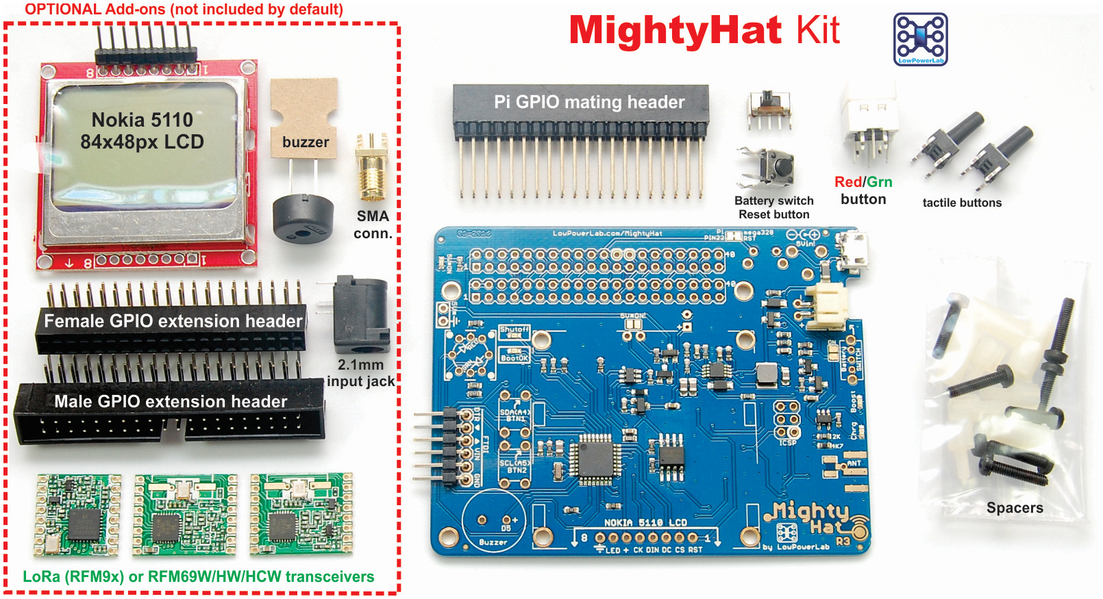
First, the extra side header is soldered, if any. It’s easiest to do this part before any other headers. The hex columns are then attached and ready for the larger header. Note that you will need to cut down the black plastic screws since they are too long – they need to allow the long+short white hex nuts to mate.

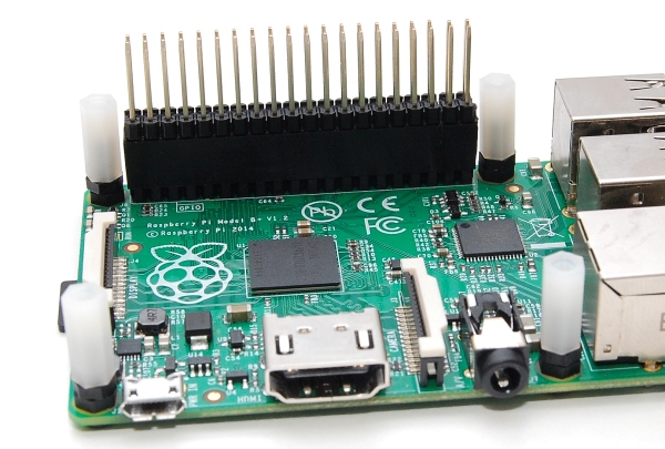
We get the Pi ready, and insert the double length mating header all the way down into the Pi header.

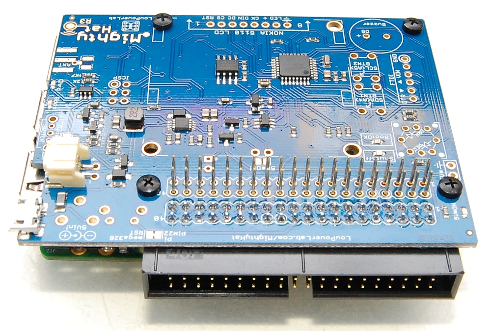
Carefully insert the MightyHat through the header.

make sure to keep the the pins of the mating header as straight as possible, or it will be difficult to align and insert all 40 pins through the MightyHat header pin holes!

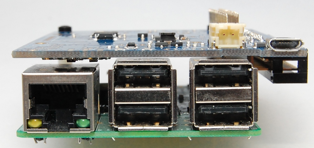
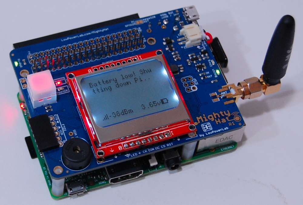
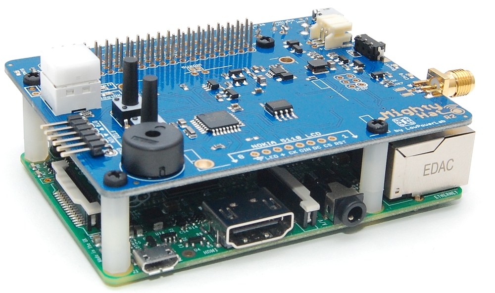
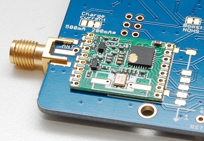
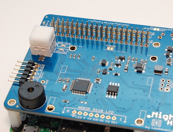
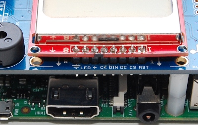
It’s very important to set the right height of the MightyHat before soldering the mating header. The plastic hex columns (~17mm height) are meant to help with this. The radio module will be just above the ethernet connector housing, but it should NOT touch it.

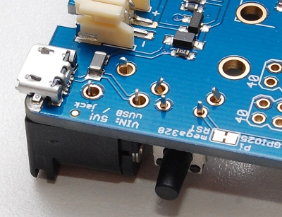
Once this is done and everything looks good, proceed to solder the header. You may only solder the pins that you actually use. The essential pins are the Power pins (pins 2,4,6), the serial pins (GPIO 14,15, aka pins 8,10), and the power control pins (GPIO 7,8 aka pins 24, 26). The rest of the pins can perhaps be left unsoldered.

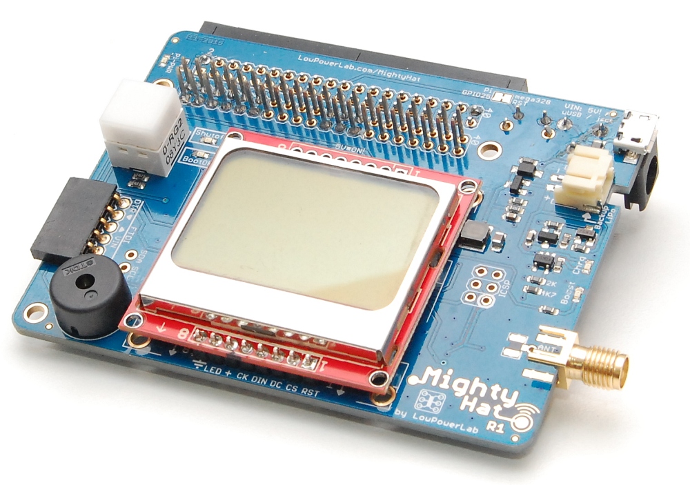
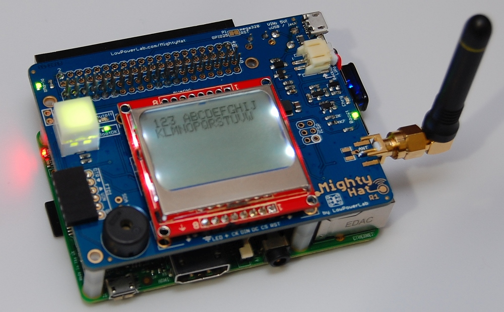
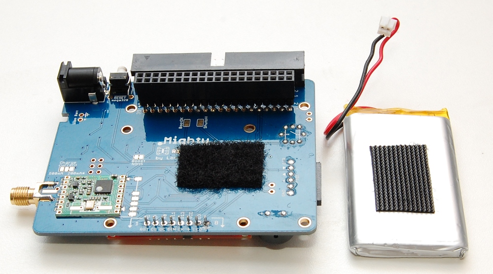
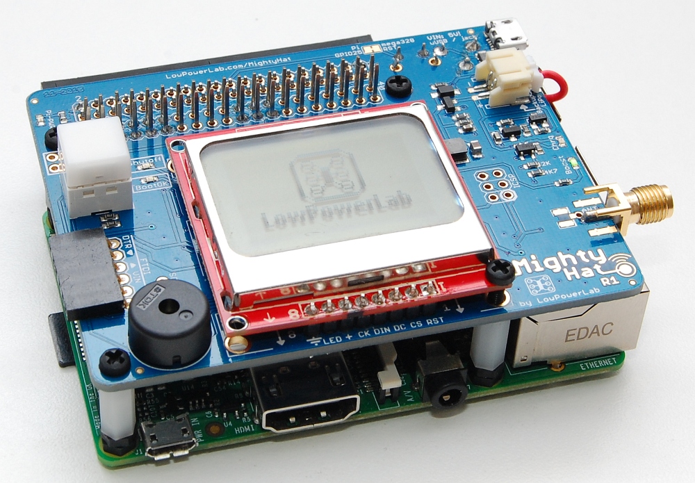
And this is the finished result:

Assembly

This is a guide to assemble, solder and install MightyHat ontop of your Raspberry Pi. Here is the complete MightyHat kit:

Start with small/short parts first and work your way to the taller/bulkier parts.

    1. Solder the transceiver and SMA connector (if any) if you haven’t had a transceiver already soldered. Make sure you orient it the right way, as shown in the photo.
    2. Solder the RST tactile button and the 2.1 power jack (if any).
    3. Solder the battery slide switch. This is useful to cut off the battery without needing to unplug it, say if you wanted to ship a Pi with a MightyHat and battery plugged but not powered/active.
    4. Solder the buzzer if you have one (either orientation is fine).
    5. Insert the Red/Green tactile button. The leads are easy to bend so be careful when you insert this one not to break them off. It also matters which way you insert it. Look at the picture and orient it with the black writing on the inside of the PCB.
      The R/G button is a tactile button that has two integrated LEDs:

      • a red LED wired to D9
      • a green LED wired to D6

      The button itself is wired to A2. While this can be used as a general purpose button, the sample sketch shows how to use it as a power button, to turn ON the 5V* output rail and power the Pi.

    6. Solder your extra extension header (if you have one).
  1. Attach the hex standoffs to your Pi mounting holes. New kits are shipped with 3D printed 17mm standoffs and M2.5 metal screws to mount on the Pi. First attach the standoffs to the MightyHat PCB, do not over tighten the screws:
  2. Insert the mating header into the Pi’s GPIO header. Then insert the MightyHat on top of that header and solder the mating header onto MightyHat.
  3. A 1000uF capacitor was included in the kit and while in most cases it might not be needed, it’s a good idea to solder it anyway. This capacitor helps with voltage dips (on the MightyHat 5V* output) if there are large loads or load spikes on your Pi, and helps prevent brown-outs. It can be mounted top or bottom, wherever you can find room for it (yielding room for the battery and LCD, if any). Just make sure you get the polarity right:
  4. Solder the LCD using the included 1×8 header. If you source your own Nokia 5110 LCD ensure the pinout order is the same as the one marked on the MightyHat mating header. The LCDs usually have 2 parallel headers, make sure to match the pin order, they are numbered, match 1 with 1, 8 with 8, only one header will match  the silkscreen numbering so be careful not to solder the wrong side of the LCD:
    NOTE about Nokia 5110 LCD: these LCDs are pressure fitted to the PCB contacts through a rubberized connector. If the metal shroud is not tight, the actual LCD might be loose and contrast or image could be compromised. You should double check this metallic shroud is secured at the back of the PCB through the 4 metal tabs. Also it’s a good idea to first solder the header to the LCD and test it out on your Arduino/Moteino with the given sketch or an example sketch in the u8glib library, to ensure proper contrast is achieved and the LCD is working. It’s easier to debug this potential issue before it is soldered to MightyHat. An alternative is to solder a ribbon cable which allows the LCD to be flipped over or more easily removed if later required.
  5. If you want the backup function to prevent a potential SD card corruption or system downtime during a power outage, you can attach a Lithium Polymer battery at any time. When external power (5V) is present, the battery is charged. If external power is lost, the battery picks up and keeps your Pi running until power comes back or until the battery runs out at which point MightyHat shuts down your Pi safely as a last resort. I recommend at least an 2Ah battery, this one from Adafruit works well. You can use velcro or double sticky tape to attach it to the bottom of MightyHat.
  6. To secure MightyHat ontop of your Pi, add the remaining 4 screws into the standoffs. Note that one is mounting hole is shared with the LCD, mount this screw first, do not over tighten this to avoid the LCD PCB to warp. For the other 3 standoffs you may need to shorten the screws to make them fit into the standoff, cut them with a razor or utility knife.
  7. Assembly done, you can now move onto the programming part!

Pi3 Serial Port Issues

This is a short guide restore the serial communication between MightyHat and your Pi3. You may also find this information in this official RaspberryPi.org UART documentation.

The new Bluetooth module on the Pi3 is configured to use the default /dev/ttyAMA0 (aka /dev/serial0) serial device on GPIO14-15. For compatibility with MightyHat, we need to disable the Bluetooth device and stop it from using that serial port. Edit the following file:

sudo nano /boot/config.txt

Add this line at the end:

dtoverlay=pi3-disable-bt

Finally, make sure the config.txt file now has this line:

enable_uart=1

Save with Ctrl-X,Y. Then run this command:

sudo systemctl disable hciuart

Reboot your Pi3. Then install minicom, and if nothing else is using the /dev/ttyAMA0 serial port, you should be able to open it in minicom and see any incoming serial data from the MightyHat (ie RF data passed through to the Pi serial port):

sudo apt-get install minicom
sudo minicom -b 19200 -D /dev/ttyAMA0

For reference and more details you may also want to read this helpful blog post that reviews the Pi3’s GPIO serial port and its usage with other hardware. There is also this blog post that discusses serial port issues on the RaspberryPi 3.

Programming MightyHat

Since MigthyHat is primarily a power controller, a power path latch ensures the Raspberry Pi is kept running whenever MightyHat is restarted/reprogrammed. This is an important feature which means that the Raspberry Pi can run undisturbed while we make any changes to the MightyHat firmware.

There are 3 ways to program MightyHat. Let’s review each one:

  1. Programming via FTDI header
    This can be done at any time, but the Pi must be turned off. This is because the serial port of the MightyHat (atmega328p) is shared with the Pi. So after the Pi is off, plug your FTDI Adapter as usual and program it as any other Moteino – ie pick Moteino (if you installed the Moteino core) or Arduino UNO from Tools>Boards in your ArduinoIDE.
    The FTDI connector can only power and program the ATmega328, it cannot power the whole board. You must connect power through uUSB and/or LiPo battery to power your Pi.
  2. Wireless Programming
    The MightyHats have an atmega328 and 4mbit FLASH MEM chip, and come with the standard DualOptiboot bootloader, which allows easy over the air programming. The sample sketch has the wireless programming token check which is required for wireless programming (just uncomment this line: #define ENABLE_WIRELESS_PROGRAMMING), see this guide on how to achieve wireless programming on MightyHat or any Moteino.
    Wireless programming is convenient when you do not have physical access to your MightyHat or RaspberryPi.
  3. Programming directly from the Pi via avrdude
    The RST pin of the atmega328p is connected to the Raspberry Pi pin 22 (GPIO 25). This gives the Pi the ability to reset the MightyHat/atmega328p, which is required to put the atmega328p in bootloader mode. This issue is covered in more detail in this article, so please read that if you want more technical details of what this really does. You will need to install avrdude and patch it so that uploads to the board can be made directly via avrdude. There is a more detailed guide here for how to install this on the MightyHat.
    For this to work the GPIO serial must be completely free and unused by any other process. Also the DTR pin has to be setup to reset the atmega328 before programming (this is what the avrdude patch does).

    Note: that a MightyHat compatible image is published for the “Moteino Framework Gateway” already has this patch, so you don’t need to do this again. Otherwise if you are installing MightyHat on your own run this command to install the patched avrdude:

    git clone https://github.com/LowPowerLab/avrdude-rpi ~/avrdude-rpi && ~/avrdude-rpi/install

    After avrdude is patched you can upload a new sketch to the MightyHat using a command such as this:

    avrdude -c arduino -p atmega328p -P /dev/ttyAMA0 -b 115200 -U flash:w:pihat.hex

    Here’s a complete avrdude programming sequence. Note the sudo stop gateway and sudo start gateway before and after the programming (this is required to free the serial port used by the gateway app, or otherwise you have to free up the serial port from any other application using it, or avrdude will fail):

Programming your Pi

Just like the ATXRaspi, the MightyHat can issue a reboot/shutdown to your Pi. The way this works is via 2 GPIO connections from/to the Pi:

  • BOOTOKfrom MightyHat’s A6 to Pi’s GPIO8 (pin #24). This pin allows the MightyHat to know your Pi’s status and when your Pi has fully booted.
  • SHUTOFF from Pi’s GPIO7 (pin #26) to MightyHat’s A3. This pin allows the MightyHat to request either a reboot (short HIGH pulse) or shutdown (permanent HIGH) to the Pi.

To allow this functionality to work you need to install a script that run’s on the Pi after boot is complete and does two things:

  • asserts BOOTOK signal to HIGH so the MightyHat knows the Pi is booted OK and ready for a reboot/shutdown command
  • listens to SHUTOFF for a reboot or shutdown from the MightyHat

The required script for the Pi is the same as the one used in ATXRaspi. If you use the PiGateway install, there is a step which allows you to install the script automatically (MightyHat should be connected to the Pi at that time). Otherwise please check this ATXRaspi guide page for installation steps with a standalone MightyHat (without or after the PiGateway setup).

The physical button with integrated red/green LEDs on the MightyHat, can control all of this functionality as seen in the MightyHat sketch. It can enable power to flow to the Pi, issue the reboot/shutdowns (if BOOTOK=HIGH) and forcefully cut off power even if the BOOTOK is LOW. The default behavior of this button is as follows:

  • reboot the Pi – press and hold for less than 1 second. Button red LED starts to blink and waits until Pi reboots and BOOTOK=HIGH, at which point it becomes green again.
  • shutdown the Pi – press and hold for more than ~2 seconds. Button red LED starts to pulse and waits until BOOTOK=LOW, then cuts power shortly afterwards.
  • a short button press (re)powers the Pi.

Possible / known issues

Unprotected LiPo cell overcharging

Symptom: you have a MightyHat R3, and using it with an unprotected LiPo cell (bare cell without embedded protection circuitry). Depending on the USB voltage, the battery might charge to above the recommended 4.2V for LiPo cells.

Solution: It is recommended at least until R4 is released to use LiPo cells with embedded protection circuitry, as that is a double protection that guards against several faults, not just overcharging.

Pi screen full of junk / corrupt text at first boot

Symptom: with your MightyHat attached, instead of booting to a login prompt, the Pi console produces endless junk text output. This is because:

  • by default the Raspbian images enable the GPIO serial console and will start sending output to the GPIO serial port (the /dev/ttyAMA0 port).
  • the MightyHat serial port is hardwired to the Pi header and once programmed, it will respond to serial input from the Pi side. The Pi will then try to interpret the incoming serial text from the Pi resulting in an endless loop

Solution: the serial link must be interrupted until you can login and disable the serial console via the raspi-config utility. There are a few ways to achieve this:

  • setup your Pi before you attach the MightyHat to it, disable the GPIO serial console via raspi-config and only then attach the MightyHat
  • if the MightyHat cannot be removed, you can hold the tactile RESET button on the MightyHat (this ensures the MightyHat is not active and the serial port is disabled) while the Pi boots to the login prompt, then run raspi-config to disable the serial console, once that is done you can release the MightyHat RESET button


CAD / Enclosure

Below is the DXF blueprint of an enclosure that will fit the R3 revision of MightyHat. You can laser-cut this from 3mm acrylic or any material that you can use in a laser cutter. Notice the settings for a 60W laser, the green area is engraved to better fit the micro USB connectors – these areas are both on the inside of the enclosure so pay close attention to the orientation of the engraving versus cutting.

Schematic