SwitchMote is a wireless light switch controller that replaces traditional mechanical switches and allows wireless control up to two AC loads. SwitchMotes can be independent of each other or they can be linked in such a way that when a button is pressed one or more SwitchMotes can turn their loads ON/OFF (via SYNC-ing).
SwitchMote PSU assembly
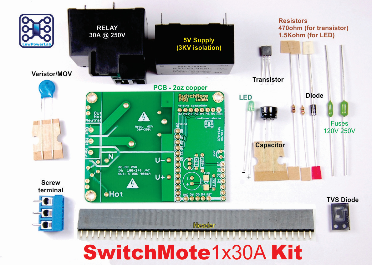
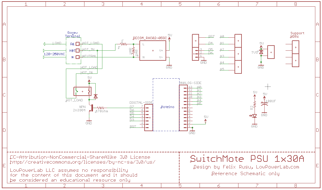
SwitchMote PSU is the power supply side of the SwitchMote which allows wireless control of a single 16A relay, or up to two 10A relays.
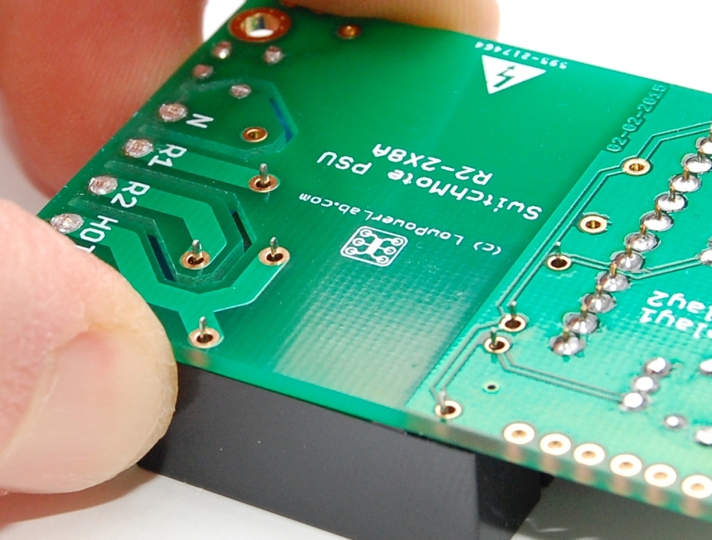
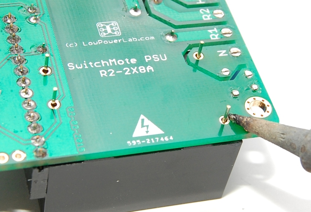
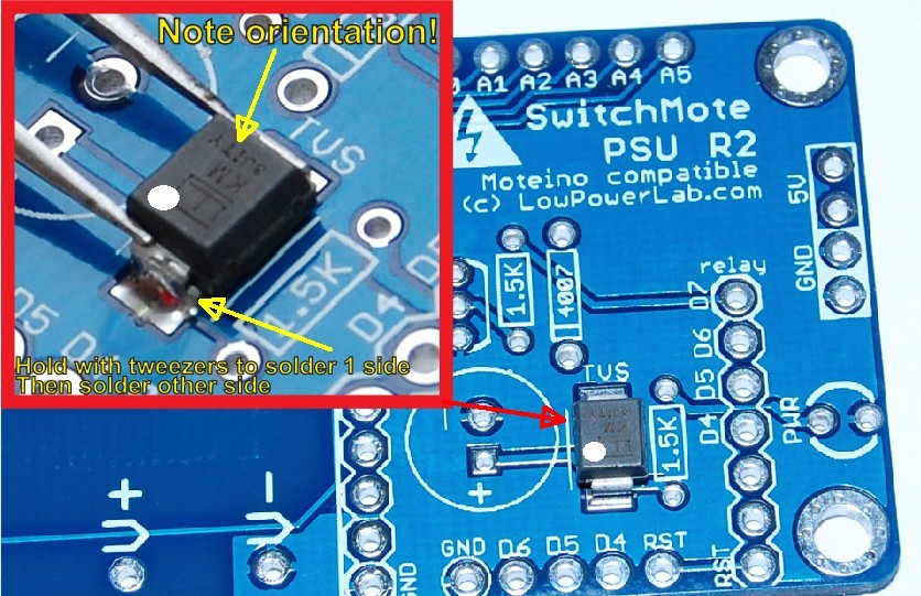
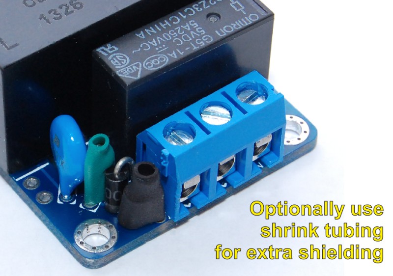
Always solder components from smallest to largest. Start by soldering the MOV (blue through hole component). Then solder the terminal header and make sure the leads access terminals are to the exterior of the board. Finally trim the leads as neat and flat to the PCB as possible.
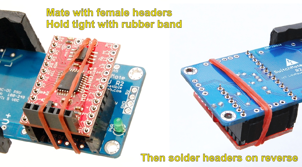
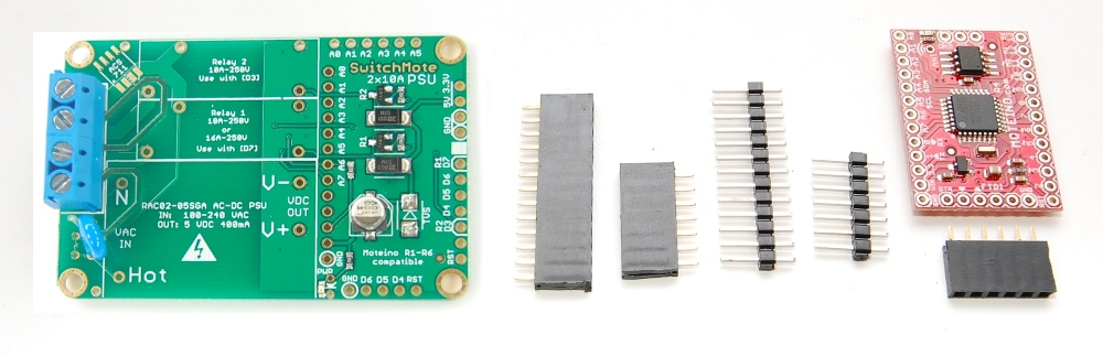
Prepare the male and female headers for mating with Moteino. Cut the provided kit headers into these segments: 1×7 and 1×13 male; 1×6, 1×7 and 1×13 female. Each time you cut a female you lose a position so to cut the 1×7 you must cut at the 8th position. Trim the excess plastic on the female headers with an utility knife. Note: the photo below shows the older R2 PSU, this is for reference only, the important part here is the headers:
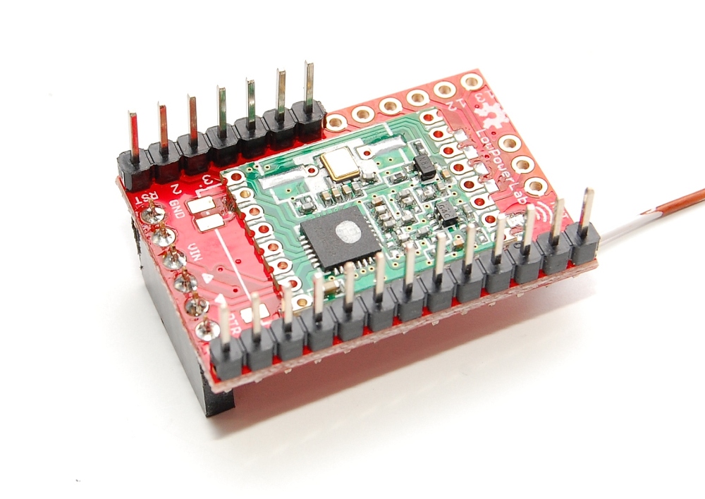
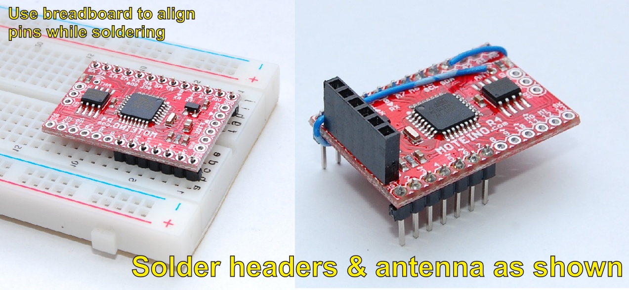
Insert the headers in the SwitchMote PCB to align them and then solder the male headers on the Moteino first. Then solder the Moteino 1×6 female FTDI header on the TOP of the PCB, see photo, also a good time to solder the wire antenna. Then proceed to solder the female headers on the SwitchMote while using the Moteino as align helper.
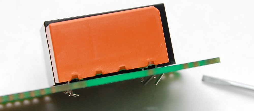
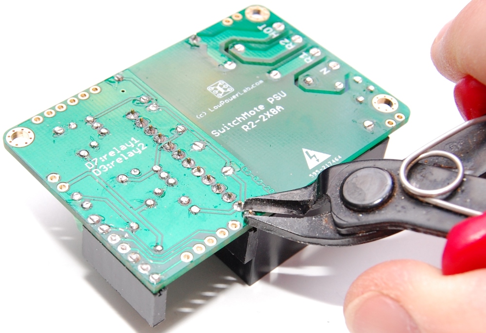
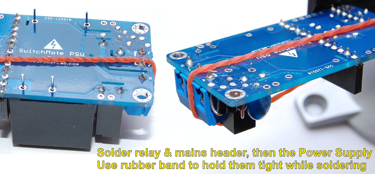
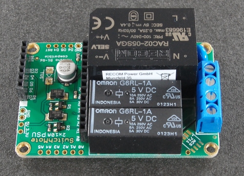
Next up is soldering the relay(s) and the RECOM power supply. If you have the single 16A relay, solder the RECOM power supply first, then cut the extra relay pins (cut them as low/flat as possible) and direct the other pins into the “Relay 1” slot as shown in the photos below. Insert the DC side first then use a screwdriver to help with slightly bending the pins on the other side to fit the holes:
If you have the 10A relays, solder the relays first then the RECOM power supply.
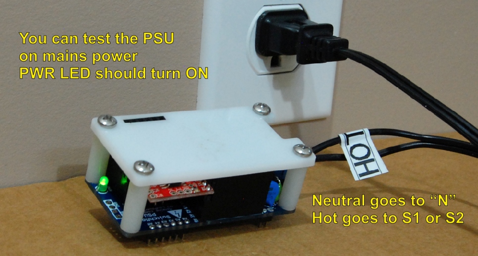
Finally trim all the leads flat and secure the antenna with a bit of tape. Then attach the PSU cover plate if was included in the kit (it’s optional with the PSU). You may/should test the PSU side if possible with a polarized power cable, insert the HOT into the “H” terminal and the NEUTRAL in the “N” terminal. The PWR LED should come on and power the Moteino (if any). You can then load a sketch and control the D7 and D3 pins on the Moteino which will control the two relays.
The photos below show the older R2 PSU but the relevant part here is soldering the large components and headers and trimming the solder joints flat.
Simple mains test with the PSU assembled. The green PWR LED should come on.

If you only have the SwitchMote PSU, then you are finished at this point.
Mating with button shield
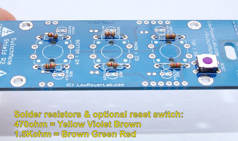
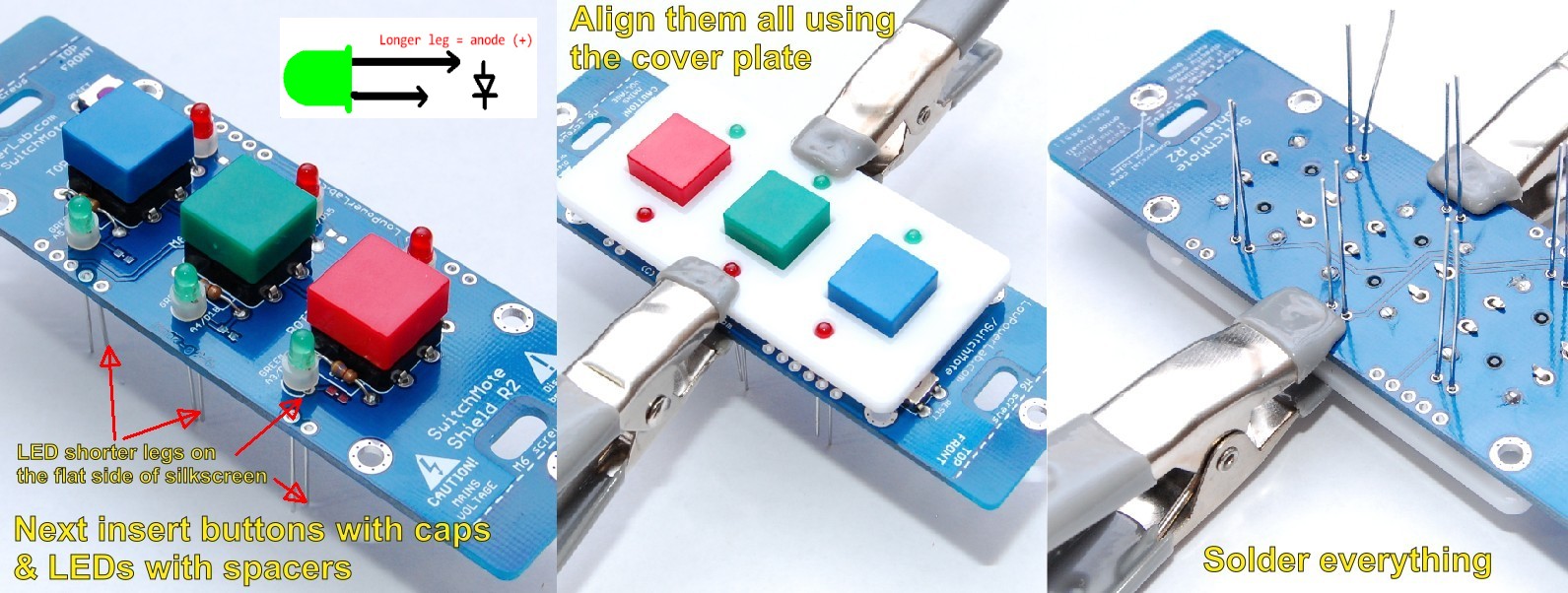
The second part is assembly of the front button PCB and mating with the PSU.
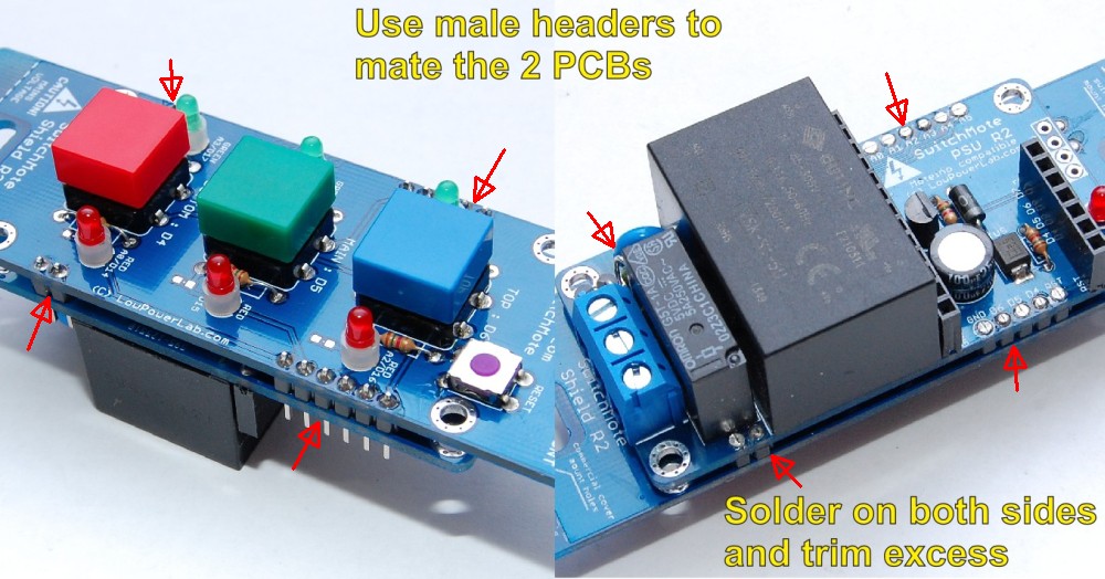
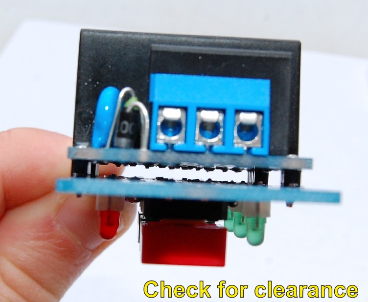
Next prepare to mate the PSU with the Shield. You will need to cut another few male headers: two 1×1, 1×5, 1×6. Mate the two parts together, ensure there is clearange between the two PCBs (no leads being close to each other, otherwise trim them down). Solder as seen in photos, when finished trim the excess of these header pins. Ensure a good soldering job with no cold solder joints.

Add the Moteino and bend antenna around in a way that it fits the case:
Add the 3D printed cover:

Button cover and final assembly
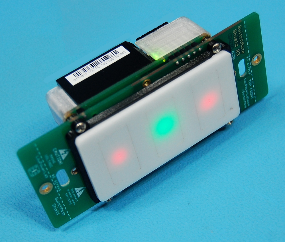
Place the lasercut acrylic button cover in the 3D printed frame, and ensure the correct orientation – RST button hole should match where the RST button is. Apply a little hot glue in 4 corners and at two points on the lateral sides as necessary, this will secure the frame to the acrylic cover:

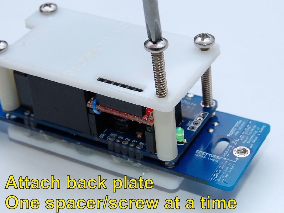
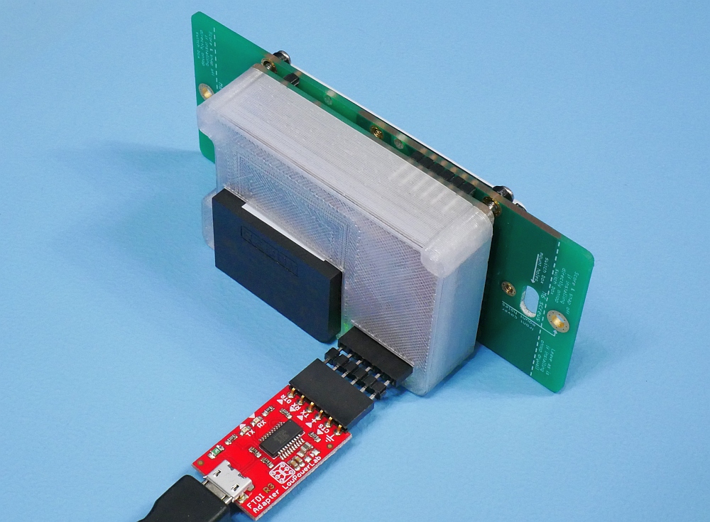
Finally, mount and mate the frame with the back enclosure with the provided screws. Avoid overtightening as this can bend the PCB and/or damage the 3D printed parts:

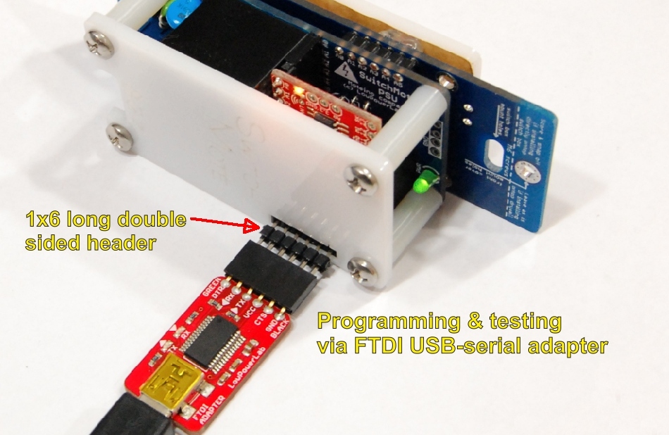
Your SwitchMote is now assembled, you may proceed to programming with an FTDI Adapter (see next step in the guide).
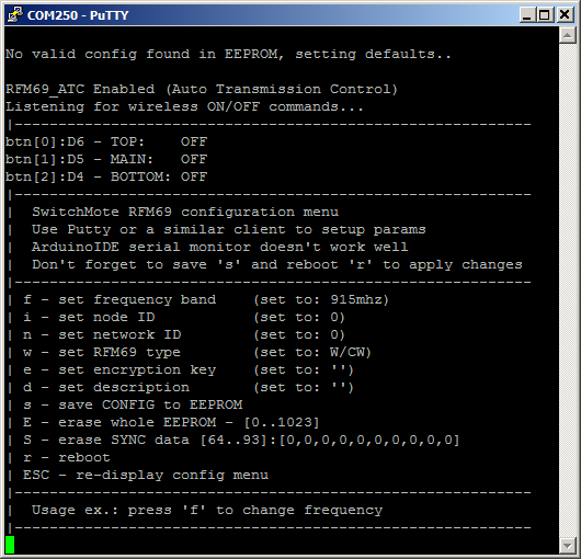
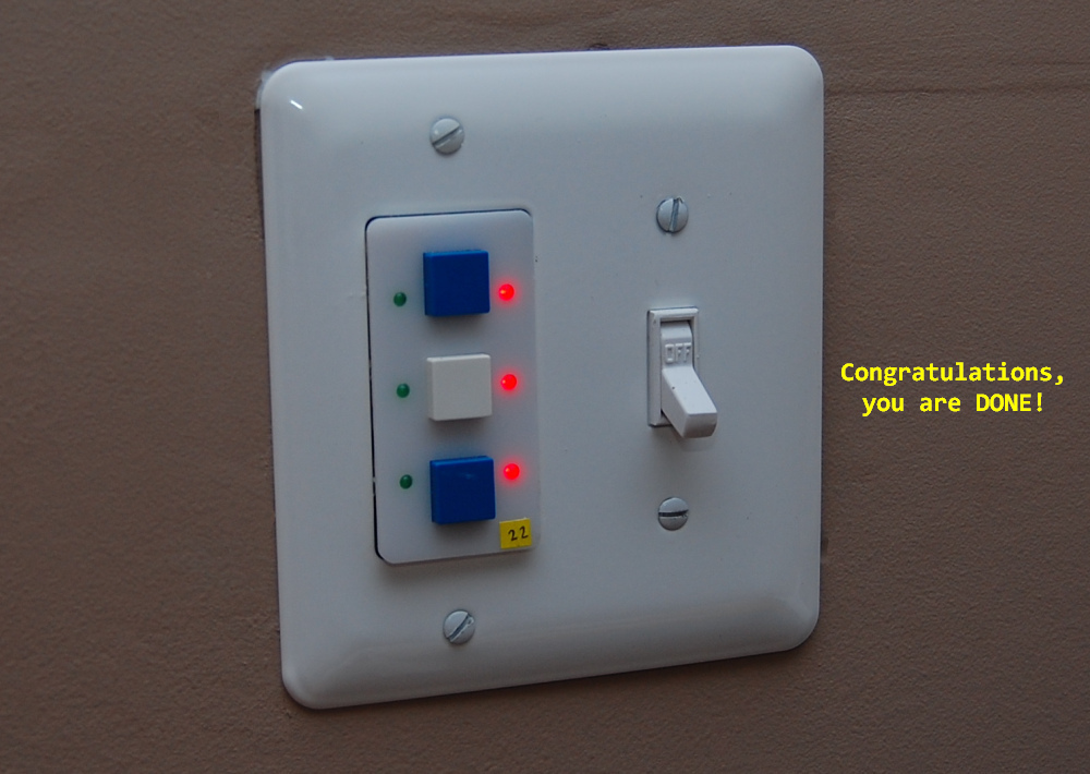
Once programmed, pressing the buttons should switch the LED states and the middle button should control relay1, top button should control relay2 (if installed).
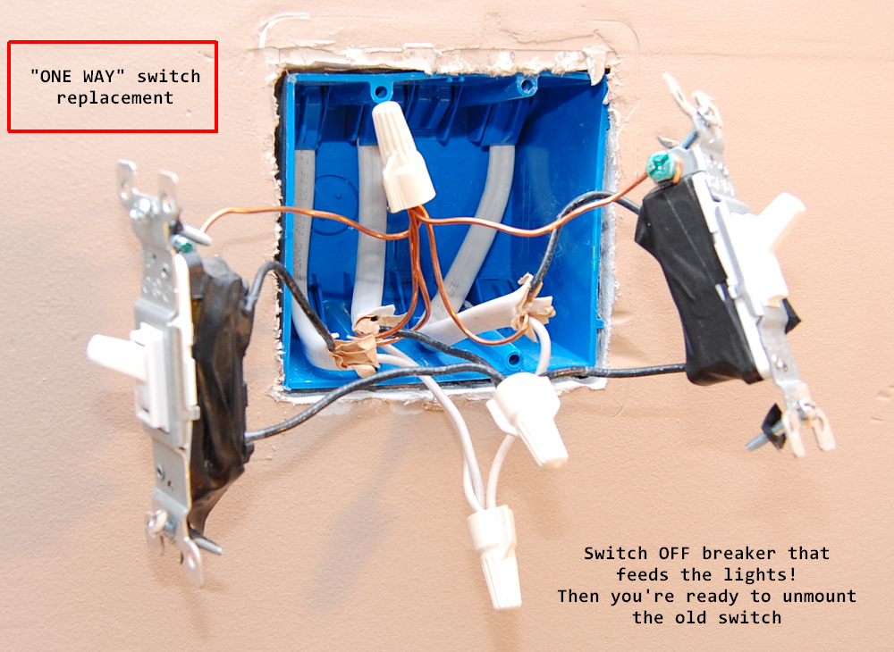
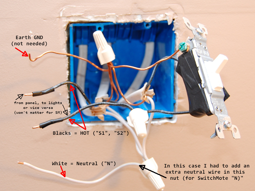
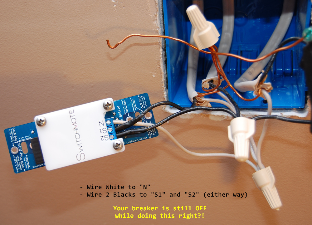
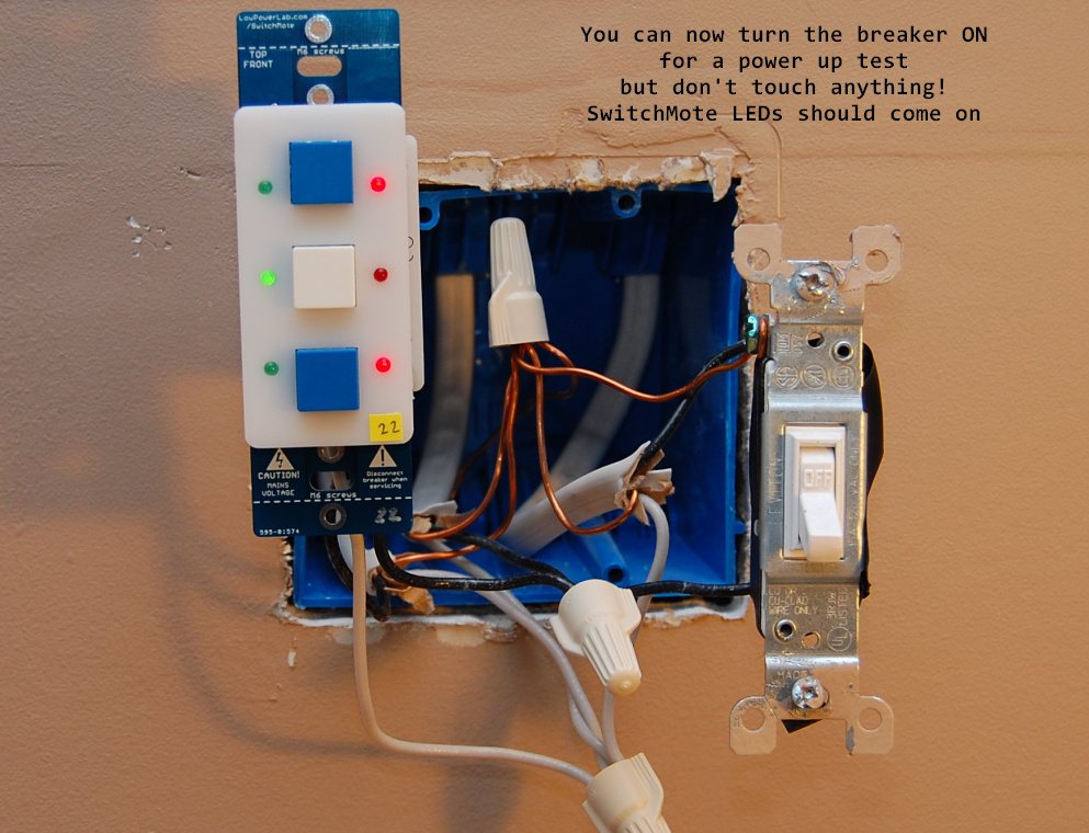
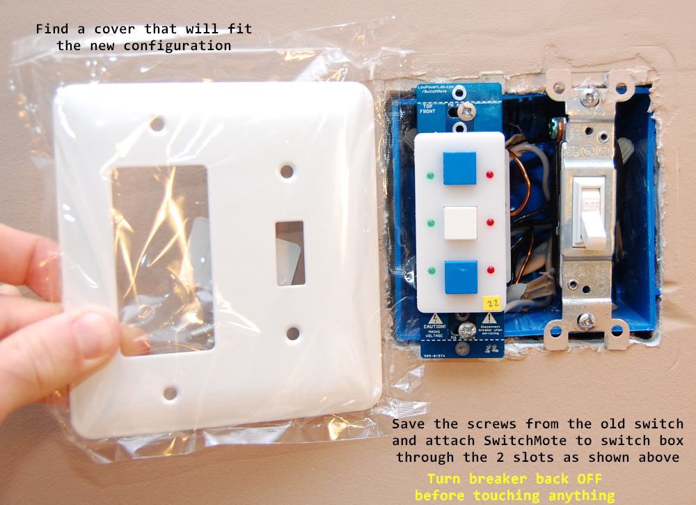
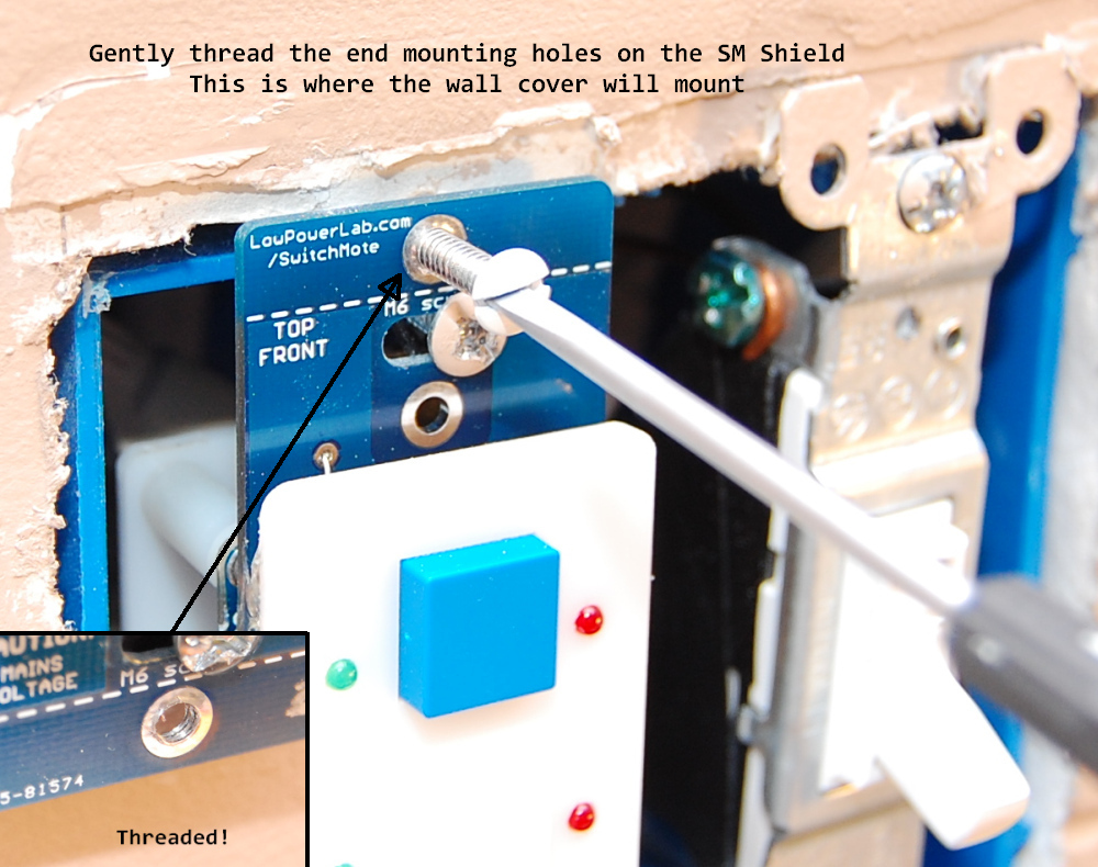
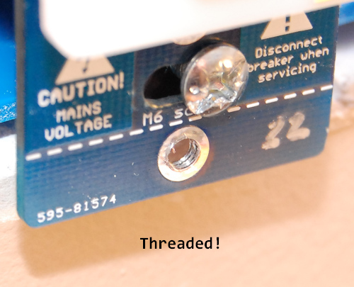
When this is all done, your SwitchMote is ready to replace a regular light switch. See the main install example page for how this might be done.