Wireless programming Moteino R3

It works!

The last few weeks I have spent a lot of time tweaking the RFM69 library and trying to get the wireless programming to work. I believe the RFM69 library is now more stable and ready for some prime time and also the wireless programming is working nicely for Moteino R3. If you think about it, being able to reprogram a mote that is 200m away, or somewhere in a tree, underground, in your attic, or on the bottom of your pool, is a pretty cool thing.

I reorganized the Github repository a little, moved some files and now the classes for wireless programming are in their own repository to avoid conflicts with the SPIFlash lib:

https://github.com/LowPowerLab/WirelessProgramming

If you have a Moteino R3 (or R2) with the onboard FLASH chip, you are ready to try programming it wirelessly, go ahead, it’s pretty neat.

The examples for Moteino R2 and R3 are in the directories for their libraries: RFM12B and RFM69.

More great stuff is coming, I got a lot of ideas for Moteino R3, I am thinking of migrating my home wireless sensor network to R3 and implementing a lot more home automation on these.

Illustrated guide to making simple jigs for programming and testing

When I built the first revision of Moteino I had to come up with a way to program and test them quickly without having to solder the headers. I saw how others built complicated jigs for this purpose with all kinds of features, so I wasn’t very excited to do something like that.

It needed to be quick and simple (without the ‘dirty’) and also without a lot of waste – spring loaded test probes (aka pogo pins) are expensive and when revisions change sometimes the positions/function of the holes change as well and I didn’t want to spend a lot of time/$ making a jig. So I just stacked two of the same PCBs as the target and used pogo pins to hold the PCBs together (or rather the PCBs to hold the pins aligned and leveled). That worked great, with one hand I could hold/press the target PCB on top of the pogo pins, with the other do the programming.

So what are ‘pogo pins’?
They are small cylinders with a piston tensioned by a spring that pushes it out and they come in all sorts of lengths, thicknesses and tip configurations (they actually have codes for each tip type and length), a picture is better than words:

spring_loaded_test_probe_pogo_pin

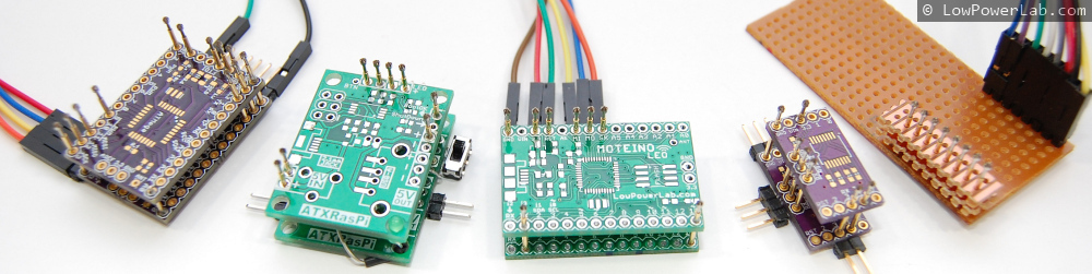
Other PCBs required testing so I built quite a few such testing jigs, here are a few examples, notice the simplicity:

programming_jig_spring_loaded_test_probe_pogo_pin

The rest of this blog entry is a guide to making jigs like these. Your final solution and it’s capabilities is only limited by your imagination. For instance you might test if a pin goes high by soldering an LED, or turn a pin HIGH/LOW by soldering a switch.

Continue reading →

Introducing ATXRaspi R2

A new revision of ATXRaspi was in the works for a long time. Based on user input and other suggestions I came up with what I think is a better incarnation of it. Special thanks to Mike from mikesmicromania for all the valuable feedback and suggestions on this new revision!

ATXRaspi_R2

Among other features:

  • all SMD components yield a more efficient layout and a leaner profile
  • More input options: microUSB, 0.1″ header, 2.1mm barrel jack
  • More output options: 0.1″ header, USB type A (female)
  • poly fuse footprint allows you to add your fuse of choice directly on the ATXRaspi (through hole or SMD)
  • onboard SMD LEDs help visualize signals between ATXRaspi and RaspberryPi
  • extra output power header pins (2x5V, 3xGND)
  • backwards compatible

This version is making a huge difference in manufacturing, as I assemble everything by hand. R1 was difficult and time consuming to assemble. While R1 worked great, the relay would be prone to voltage spikes and drops depending on the quality of the input supply, hence causing glitches and requiring multiple button presses to turn power on (an effect that was reduced by wrapping the output power wire around a ferrite bead). This new design uses a mosfet which drops only 10-15mV of power and these effects should not be manifested any more.

Just for fun, here’s the stencil I produced for ATXRaspi R2 with my DIY stencil method, and the results after paste application:

Please use the forum to submit more feedback and suggestions which are always welcome!

RFM69 library and Moteino R3

This is the library that I’ve been working on for the new RFM69 modules from HopeRF. I consider this an initial beta release and it surely is a work in progress, it may contain bugs, but the provided Gateway and Node examples should work out of the box and illustrate basic usage. Please let me know if you find issues. The syntax is a little similar to that of the RFM12B library, but I went with some new conventions on naming and overall structure to improve readability and overall code quality.

This is a video introduction to Moteino R3:

This is a new product and the library needs more testing and performance tuning. The library currently is tuned for fixed 433/868/915 Mhz frequencies, and a 50khz bitrate, 50khz frequency deviation. I am hoping others will contribute and test the library to find the best combination of these settings and power level vs range vs frequency vs bitrate, etc.

Continue reading →

From china, with love: bad solder paste

Recently I was running out of solder paste and I’ve bought some chinese paste to try out from a (very) popular online electronics outlet. I think somewhere in the reviews or in one of the tutorials they say they actually use that paste internally so I got confident and the price was right (I guess… even though I later found the same paste on dx.com for under $5), about $14 for a jar of 50g which would last a long time. Great I thought, I’d get it in time to assemble more boards, without the insane shipping delays from china, so I ordered and got peace of mind.

A few days later I got it and I assembled a batch of boards with it and peeked through the microscope to inspect how it reflowed. Here’s what I saw:

bad_solder_paste

Holy cow! What happened? Tons of tiny balls of solder stuck in tons of solder paste residue. Not one of my best days, but certainly memorable. Continue reading →

MoteinoLeo: new LowPowerLab family member

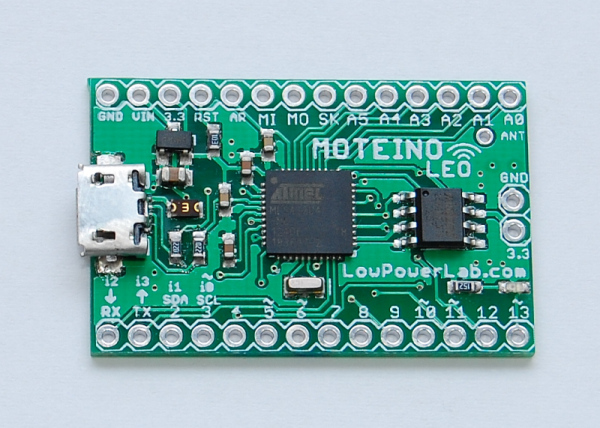
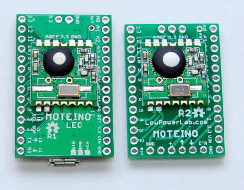
MoteinoLeo_R1_withFlash

Update: MoteinoLeo is now discontinued and no longer available for sale.


The difference between MoteinoLeo and the regular Moteino is pretty obvious – it’s got built in USB. It’s conceptually an Arduino Leonardo clone, with an RFM12B transceiver solderable on the bottom, with a few minor changes and some added features. It runs at 16Mhz, 3.3v, has an optional FLASH footprint for data logging (wireless programming on Leo is not yet achieved, perhaps in the future if a custom bootloader will permit). There’s also a 750mA PTC fuse to protect the USB against shorts or over current.

Design files are on the MoteinoLeo Github repository.

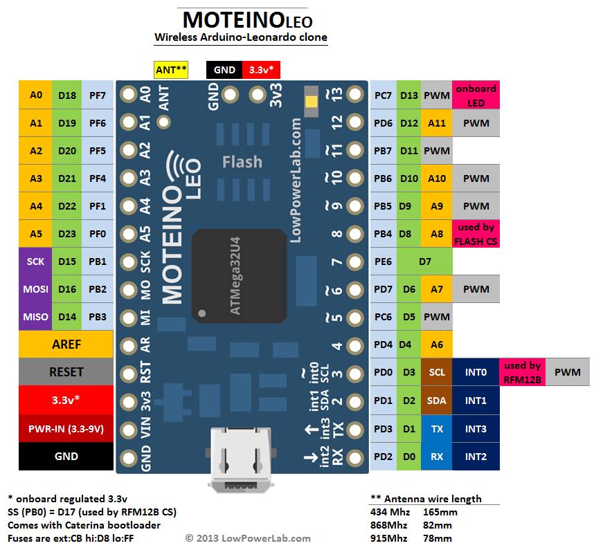
Here’s a pinout diagram:

MoteinoLeo_PINOUT

Compared to Moteino:

MoteinoLeo_top_comparedMoteinoLeo_bottom_compared_small

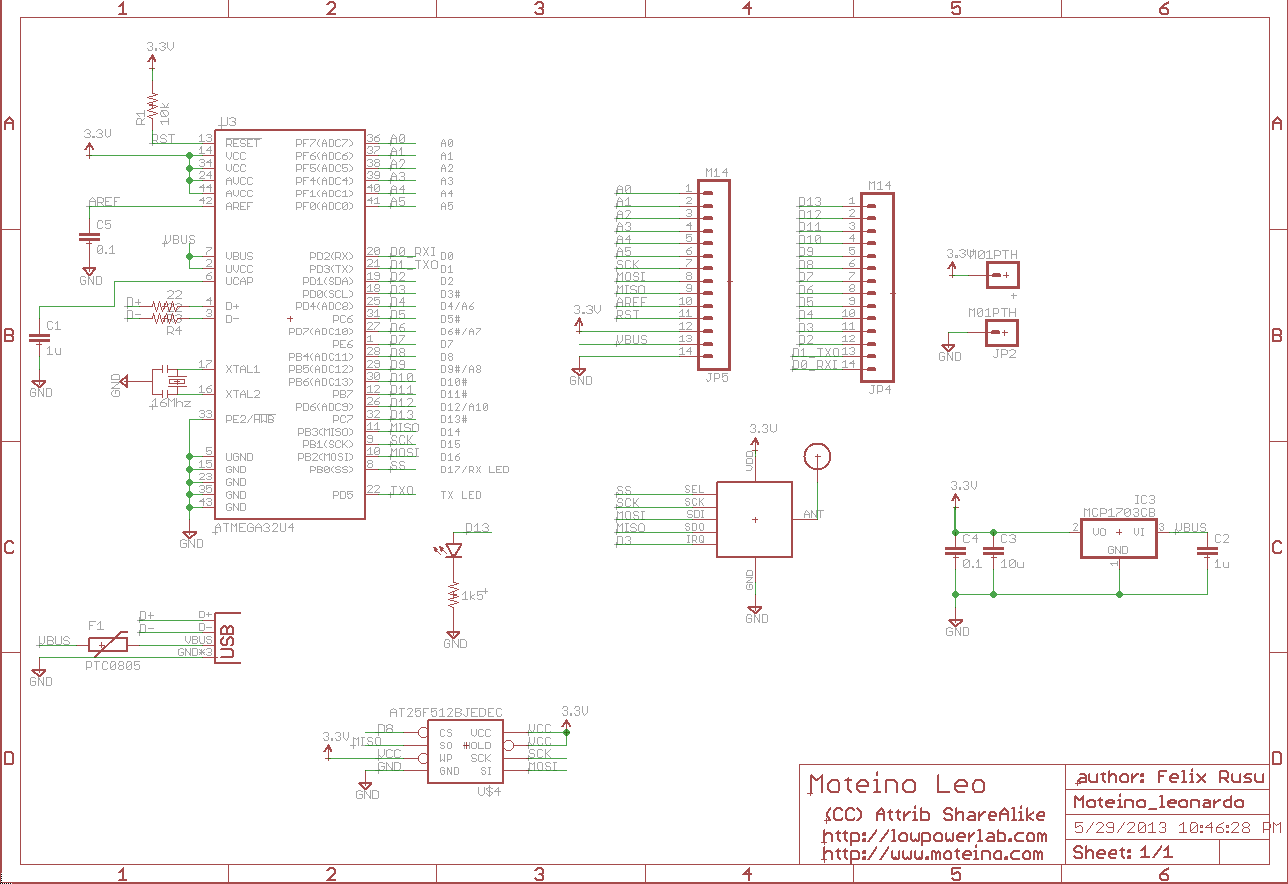
Schematic:

schematic_R1

Forum now open

I added a forum for open discussion and support at http://lowpowerlab.com/forum

This was suggested and it makes sense because all the support email I get is mounting and I find myself repeating a lot of answers to common support issues.

So please use the forum if you have an issue with LowPowerLab projects or products. I will try my best to respond in a timely manner.

Also please share your projects using Moteino or any other experience you think might be relevant.

FTDI adapter now available

UPDATE: Eagle schematic and layout are in their github repo.
There is now also a Moteino-USB version which includes the FTDI adapter and the Moteino all in one at a combined lower price.

Some people have been asking for FTDI adapters for programming Moteinos to avoid having to buy them from another store and hence pay shipping/handling twice. So I created one. It’s actually based on the Adafruit FTDI-friend which was a very good design. Here are the features:

  • 5V power level (default) – adjustable to 3V
  • 3V logic level (default) – adjustable to 5V
  • pin 6 is RTS (default) – adjustable to DTR
  • RX/TX LEDs
  • The pinout is standard [ GND – CTS – VCC – TX – RX – RTS ] and will work with any Arduino clone that has this as a programming interface.
  • compact layout

The underside of the board contains some jumpers that are shorted for the default settings mentioned above (5V power level, 3V logic level, pin6 = RTS) – these are standard settings that come with the FTDI cables and should work in most instances. Hackers may want to switch these settings – for this the default shorts need to be cut with a razor blade and the other jumper needs to be shorted by soldering the jumper pads together.

I’m working on sourcing some USB cables to go with these soon. Here are more images and the schematic:

DSC_0640DSC_0643_logo
DSC_0641Schematic


Wireless programming update

The initial code commit for wireless programming was a little sluggish and the performance wasn’t very good. I had to add delays to make sure everything was synch-ed and the protocol was working. The result was a rather slow wireless upload of a new sketch, especially if it was a large sketch. But it worked…

Today I worked on improving the protocol and was able to cut down the over-the-air upload time by a factor of ~5. The gains are mostly from improved serial communication. This will still take about twice as long as normal sketch uploads by means of an FTDI adapter. For instance, a 9,8Kbyte sketch takes me about 11 seconds to upload directly to a Moteino using an FTDI cable; wirelessly programming that same sketch takes about 22 seconds. Not bad given how involved the whole handshaking protocol works. And much better than almost 1 minute with the old code. So I’m classifying this new release as a beta. More improvements or bug fixes might be added later, but it’s definitely a functional release. I’ve uploaded different sketches of around 10KB several times without a glitch.

The wireless sketches examples (gateway and node) and the python script are in their github repo. The SPIFlash library was also updated (the WirelessHEX part of it), so get latest before you try this.

As mentioned before, the target node of the wireless programming protocol will need to have an SPI Flash chip attached (if they don’t have one already), and also run the DualOptiboot bootloader for this to work. Moteinos come with this bootloader (all orders since the other Wireless Programming post and code was released). If you have all these components right, any Arduino clone with an RFM12B transceiver and an SPI Flash chip of at least 32Kbytes of memory will do the job.

Just for fun, here’s how the end of a wireless upload looks like, notice there were 617 packets sent all the way from the PC (through the python script) to the attached Moteino (gateway), wirelessly to the remote Moteino (target node):

Transmission_end