UPDATE: Check out the new version of this, now with bell enable/disable function!
A lonely doorbell activated by a boring push-button at the front door is not very exciting in a world of Arduino and “Internet of Things”. I’ve been wanting to Arduinize the doorbell into the Moteino Framework gateway interface so that I could:
- observe/count/graph when the doorbell is used
- get notified when someone rings it if I am not at home (email, SMS etc)
- play a sound when I am in my lab where I have a hard time hearing the chime (did I hear it or not? should I go upstairs to check? nah… I’m too busy for that)
- ring the bell if I want to, *remotely* from your mobile device (why not right? just detecting is too boring)
Below is a schematic of what a typical wired door bell circuit looks like, and also a photo of what it looks like in my house. The dotted green rectangle is the circuit that I have physical access to – pictured next to it in my basement (and I don’t have a back door button):
 | 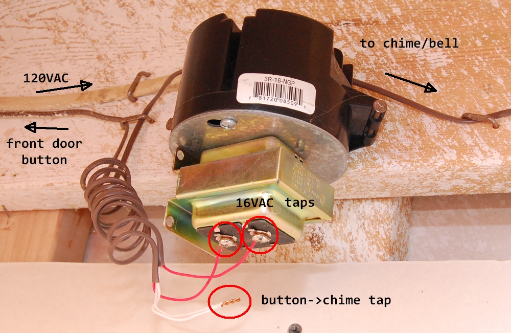 |
I have a single button (front door) and probably most houses do. So I only care to inject my solution for that front door button. There is typically a 16VAC transformer powered from mains that activates the chime when the switch is pressed. So there are a few issues to solve in order to tap into this circuit, detect button presses and also being able to control it via Moteino:
- Power our circuit from the 16VAC doorbell transformer. This is a good exercise to create a DC power source from an AC source. We’ll use a simple half wave rectifier to achieve this
- Detect when this 16VAC current flows through the wire coming from the outside button. When the button is pressed, the chime will ring and our circuit detects the AC current and outputs a digital HIGH for the Moteino input pin that monitors it
- Make the Moteino “press” the door bell button when it receives a “RING” wireless message
I will explain these points step by step. Let’s get to work! Continue reading