Simple monopole antenna testing

As outlined in the RF Best Practices guide, the Monopole Antenna is formed by a quarter wavelength vertical piece of wire, plus a “launchpad” ground around its base, and is a very good cost-to-performance ratio antenna. The quarter wavelength refers to the wavelength of the frequency at which the radio is transmitting/receiving. As an example, the for 433mhz the wavelength is 0.69m and the quarter wave is then ~172.5mm. This is a theoretical figure at which the signal would have maximum resonance in the antenna, but in real life the signal from a radio goes through various passive components (matching networks), RF switches, and other PCB traces which influence this signal, and hence the signal might resonate better at slightly different physical dimensions of the antenna.

In the video below, Marcel illustrates how you can test a simple monopole antenna by starting with a given length and then trimming the antenna length to determine which length yields the longest range. Since the radio can transmit at a maximum of 20dBm, a 30dB attenuator was added and also the transmit power was diminished in software (with this function) to reduce the total output to around -26dBm – that is many many times (-30dB = 1000 times reduction) less powerful than 20dBm (dB scale is logarithmic not linear – see this page for more on that). This allows testing the antenna at very small range without having to walk very far away to see the signal drop. The monopole is omnidirectional in the horizontal plane (ie it emits the signal in all directions at the same intensity).

Of course, this type of test could be done in the lab with a VNA (Vector Network Analyzer). But for such a cheap and simple antenna, this test shows how easy it is to do it yourself without investing an eye watering amount of cash in such exotic equipment.

You can do your own testing in a similar manner, and you can even use the Node and Gateway examples for this purpose, and simply add the setPowerLevel(0) call in setup() (and disable RFM69_ATC) to reduce signal power, or use an attenuator like Marcel did. Be sure to check out this page where Marcel has used the same technique to test several antenna types, with some interesting results – this might help you decide to upgrade from the virtually free monopole to a dipole.

SwitchMote with single 16A relay

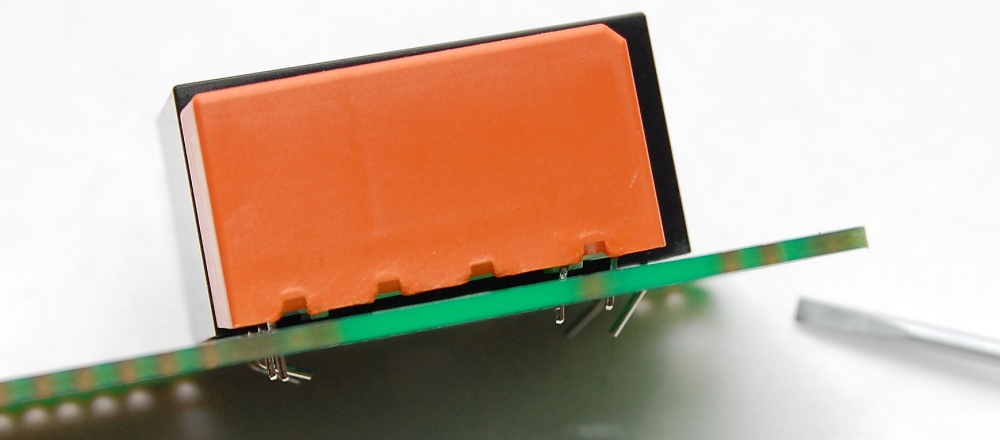
SwitchMote  and SwitchMote PSU are now available with a single 16A relay, instead of dual 10A relays. I realize this is most often the case that a second relay is not really necessary, except when replacing dual gang switches with a single gang SwitchMote, so I found this higher rating relay which can be soldered as shown in the guide. I also added the option to get it with a single 10A relay since most light applications now use either CFLs or LEDs and 16 amps are not really necessary for such small loads.

This new 16A relay requires removing two of the leads to make it fit the SwitchMote PCB, this is also added to the guide:

Worth noting here that the dual relay SwitchMote (a.k.a. 2x10A) is now the official kit that deprecates the older single 5A relay SwitchMote – that one has been discontinued and will only be available by special order.

Sump Pump Watchdog hack


The sump pump is a device that works hard to keep your home dry but is prone to failure, and if you have any valuables in your basement or crawlspace, even a light flood can cause a lot of damage and potential health problems (mold!). It tends to fail in a big storm when it gets really busy pumping water away from around your home (worse if you lose power too). Heard a few horror stories and not having some kind of backup or monitoring it is the perfect recipe for a disaster waiting to happen.

My trusty SonarMote is of course an independent sensor which alerts me when the water reaches an unsafe level in the sump well. It’s mounted on the bottom of the sump well lid and it measures the distance to the water surface. My gateway app graphs that level and also provides a means to alert me via SMS or email.

This year the pump’s mechanical float decided to get stuck again and then fail, so I had to either buy a whole new pump, or find an alternative to the float part. Turns out there’s a device called The Basement Watchdog. It’s very simple in its operation – has its own float, which triggers a circuit that activates a 120v outlet for a fixed amount of time, cheap and perfect.

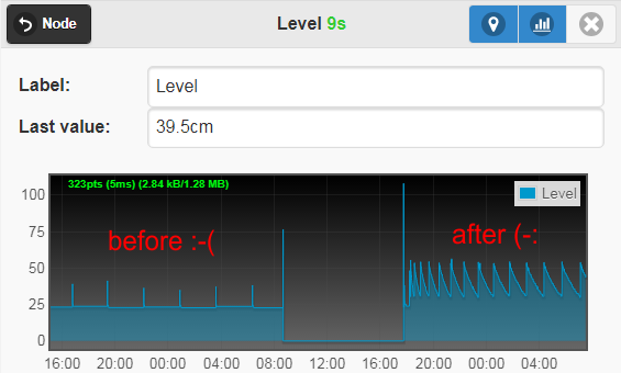
As soon as I installed this, I noticed my SonarMote measurement graph was messed up. That’s because the device would tend to empty out the well very sporadically and for a short delay, and the level would only vary by very little, not very visually helpful.I wondered how hard can it be to hack the Watchdog to make it stay on for longer and pump more water. Unsurprisingly the circuit is based on the TI ne555 timer chip which after a little investigation is obviously running in monostable configuration. Here’s a nice video walkthrough that explains this mode in more detail if you’re not familiar with the 555 timer. In a nutshell there is a trigger (the float) which activates the 555 timer output to go HIGH (activates relay and turns pump ON) for a fixed amount of time (configured by a resistor and capacitor RC discharge circuit), after which it goes LOW (and switches off the pump).In my Watchdog, the timer is determined by a 100K 200K resistor and 47uF capacitor. The 555 monostable timer formula is Tw=1.1*R*C which results in a ~5 second activation of the pump, which is way too low and explains the unappealing graphs I’ve been getting:

To change this output time there are 2 options – desolder the resistor and solder a larger value (a bit messy and risking to damage the circuit), or solder a parallel capacitor to the existing one. I chose to solder another capacitor since capacitors in parallel combine their capacitance and required no desoldering. So adding 2 wires to the existing cap and using another cap at the other end makes it easy to change the cap overall value or even use a variable capacitor. If you wanted to change the resistor instead, you could add a potentiometer and case-mount to to allow changing the timing any time later, but I thought that’s overkill, I just needed a bit longer delay. So here’s the 220uF capacitor I added and taped to the relay to prevent any movement/shorts:

Simple enough, the result was an increase to ~30 seconds which empties out the well almost completely and yields nice graphs again, I don’t anticipate having to ever touch this again:

This is the graph for one day, from empty to trigger point:

This is also helpful to see weather patterns, here’s a dry period followed by a few days of heavy rain:


Moteino R6 released

After Moteino R4 has been the long running champion of its lineup, and R5 has had a brief period of glory, Moteino has now been shipping for the past week at revision R6!

Wait, what happened to R5 which was never announced you ask?
Well R5 was mainly a transceiver layout change from R4, it also added a u.FL RF connector (which is now offered in the shop) and SMA connector “helper” pads, and few other minor layout changes, nothing too significant and otherwise identical to R4. Customers were now getting HCW and LoRa radios on the same Moteino PCB instead of separate PCBs for HW and LoRa.

However in R6 there are more important changes:

  • CW transceiver layout has been added in addition to the RFM69/LoRa layout, which means that the whole spectrum of RFM69 and LoRa radios are supported. Note that W and HW, while still in the shop, are no longer available as an option for MoteinoR6 – they are replaced by CW and HCW (which are 100% equivalent from a software and features perspective, but smaller!)
  • supported transceivers: RFM69CW, RFM69HCW, RFM95/96/LoRa
  • in addition to this, RFM12B is now also usable (though not sold) with Moteino R6 because of the new CW pads. Note that the RFM12B library is still usable but no longer actively developed or supported
  • a delay cap was added to DTR to avoid situations where the Moteino never wakes from an ultra low power state – this has been mentioned and discussed in the forum
  • u.FL pads kept for those who want to connect a pigtail instead of straight coax or the provided monopole wire antenna
  • the Trace Antenna variant reflects all these changes as well except it’s connected to the onboard PCB antenna and does not require an external antenna

Here are RF connector options now possible on the Moteino, all these RF connectors are available in the shop for convenience:


Wireless Programming updates

In past times (see this and this post), wireless programming of a remote Moteino used to be done via a python script. This took a compiled Moteino sketch (hex file) and passed it to a programmer Moteino which would relay it to the target node . Later this python app was migrated to a windows desktop app (see release post and upload speed update). At which point non-windows folks were left with a somewhat out of date python script. I was asked about the status of the python app many times. So I decided to merge the python script and windows app so all platforms can use it. This was done via IronPython which can invoke a python script straight from a windows app. Hence wireless programming for Moteinos has gone through several changes:

  • the firmware part which used to be a separate library and has been merged into the RFM69 library, this is now called RFM69_OTA.h (vs: WirelessHEX.h) and all functions have the same name and parameters
  • the windows app now can run both natively (windows code) or invoke a new updated OTA.py python app which you can control and modify if you’d like

This is the best of both worlds. The new OTA.py script is cross platform and independent of the windows app, just needs to be invoked with the right parameters (run `python OTA.py -h` for details). Those on windows can just use the desktop app (runs the protocol in native C# code), or can click the “Run OTA.py” checkbox to instead invoke the OTA.py script dynamically. The parameters are passed from the desktop app into OTA.py and the desktop app conveniently remembers your programming parameters next time you open it.

Most significantly the WirelessProgramming.exe is now 3.8MB (vs 29KB) because it bundles all the required self contained IronPython runtime to run the OTA.py script. It also requires the pythonLibs.zip file that was added in the same directory.

Give this free tool a try and let me know if there are any issues or bugs. Enjoy!


GarageMote 3D printed case

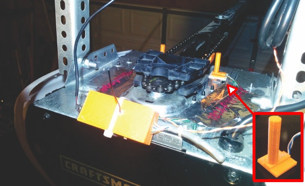
Forum user [aw] has graciously shared a 3D printed case for GarageMote. If you have a 3D printer you can download and customize/print the model from thingiverse. The model includes the option for a chain magnet snap-on which is really convenient for chain driven garage openers.

Update: a sensor pylon is now available also, which can conveniently hold the hall effect sensor for the magnet holder, a very nice addition. The kit sensor is omnipolar so it will detect the magnet in either direction.

SwitchMote latest features & R&D

I’ve long wanted to make a professional enclosure for SwitchMote and do away with the acrylic covers and all the screws and spacers. All these parts add a lot of overhead and cost to the kit.

SwitchMote was designed to be a DIY modular/hackable/educational kit (so far at least) that uses mostly “off the shelf” parts. In the past months I’ve invested into a SwitchMote enclosure design. The PSU side would be cool in clear plastic, below is a rendering:

The good news is this can be made very solid and simply snaps onto the top and bottom PCBs with some cleverly designed tabs, without the need to use any spacers or screws or other exotic mating methods. I like to simplify and KISS everything. The enclosure can also accomodate the recently released PIR option, below is a prototype:

The bad news is the eye watering cost to make the moldings for this. The cost of UL certified fire retardant material is also expensive. I would need to put SwitchMote in HomeDepot or go to Shark Tank for that to make financial sense. So at this point I’m looking at alternatives, one option is silicone molds that can produce a few hundred units at most.

Another option is to go the 3D printing route and make these right here in the shop. I’ve had a prototype built on an FDM printer and I’m quite happy with the quality and strength, the downside is detail. Because the front panel is the only exposed part, that could be covered in something else that is nice and smooth, and perhaps allow for any color the user wants.

There are many other ideas cooking as to make SwitchMote more feature rich, realiable and easy to use. For now an enclosure would be one step closer to professional looking (yet Arduino based) IoT switch (that doesn’t suck).

Ideas, suggestions, feedback and help are always welcome!

SwitchMote PIR motion sensor option

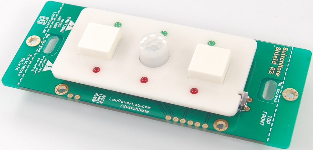
Quite excited to announce the new PIR sensor option on SwitchMote, this was requested by a user and is finally available in the shop. The chosen PIR sensor was the ultra low power Panasonic EKMB1201111 (same as offered in the MotionMote Kit). It’s a fantastic sensor, very small fully contained package, the only down side is these sensors are expensive. For this reason the kit is now significantly discounted for a limited time! You may source your own PIR of course (and mention you want the PIR parts at checkout), a forum user reported the older revision of these sensors might be found for cheap on eBay.

The SwitchMote Guide was updated with instructions for this change. Mainly the kit will come with 2 buttons and the PIR instead of 3 buttons, along with a required 10K pullup and the front cover matching the PIR sensor. Here is the updated kit content, notice the front PCB is different:

RaspberryPi Power Button Case for ATXRaspi

Looking for a sleek RaspberryPi enclosure that also fits the ATXRaspi smart Pi power controller and a power button? Check this awesome case from C4Labs which is designed to fit the ATXRaspi along with a power button for shutdown/reboot:

It includes a bunch of accessories like the power button, heatsinks and rubber feet. Made in the great again USA. Check out the new ATXRaspi Guide for the latest updates which include the ability to use both momentary and latching switches!

DHL Express for international orders

Good news for international customers!
After a period of integration and API testing, DHL Express is now available for international orders!

Pricing on DHL shipments is dynamically fetched at checkout and ranges typically from $25 to $40 to most EU countries. In almost every case it will beat the USPS pricing of PRIORITY ($33 to most countries) and it totally obsoletes USPS EXPRESS ($60 for most destinations). The transit time is typically 4 days to western EU and about 5 days to eastern EU. Most other places should expect a similar transit duration. There will always be flawless full tracking to the destination address, as opposed to postal tracking which is only available to a few countries that have agreements with USPS and has recently been unexpectedly removed from countries like France, Italy, Denmark and others.

USPS will continue to be available as flat rate service. The big disadvantage of USPS for international shipments is that there is an exchange to the destination country’s postal system, and in many cases these government run postal systems are poor at best. This sometimes results in delays, invalid package routing, invalid or confusing or out of order tracking (if any), bad customs handling and overall poor customer experience – not because USPS didn’t do its part. But because countries like Germany (the irony is the Deutsche Post owns DHL!) or Italy have very poor and anal customs which are nothing but deterrents for using the regular post for shipping.

With DHL all this is a thing of the past because DHL is one of the (if not the) best (and fastest) courier service available. It handles the customs clearance brokerage for the end customer (sounds like it may add a fee for this service in some places) but the experience you get is incomparable to that of dealing with the local post office. International buyers still have to pay import taxes as required by your country laws.

This is still considered to be a Beta release and while integration and automation continues to be implemented in the backend and some details ironed out, you are encouraged to report any bugs or issues or provide any feedback for improvement. Hopefully DHL will improve shipping experience for those customers who opt for and are willing to pay for the better service!