Sump pump alert with Moteino & HC-SR04

UPDATE: This project has been replaced/updated with SonarMote. See this blog post for a more rencent implementation of what you see here. The alerts are now implemented as simple events on the Moteino Gateway.

Here’s another project I wanted to do for a long time. I wanted a sump pump flood warning alert system in place, for peace of mind when I’m gone from home for prolonged periods. For whatever reason I thought this was going to be more difficult but no, it’s almost as easy as pie!

All I needed was a HC-SR04 sonar sensor and a USB 5V wall supply. The sensor only works at 5V so this method of powering the Moteino was very convenient since I already have an outlet close by for the sump pump.

The sensor has 4 pins clearly marked: VCC, GND, TRIG and ECHO. I connected VCC to VIN on Moteino, ECHO goes to D3 and TRIG to D4.
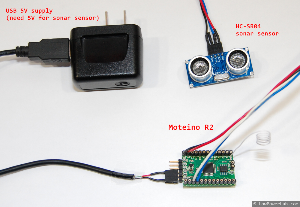
Moteino_HC-SR04_SumpPumpAlert

I used some of the code this instructable to get started and added my wireless code to handle packets and blink the LED and was done in no time. The setup was very simple, I estimated a good spot underneath the sump pump cover where there are no obstructions inside, cleaned it up, taped some velcro, secured the wires and that was pretty much it.

 Moteino_HC-SR04_SumpPumpAlert_cover Moteino_HC-SR04_SumpPumpAlert_installed

I added a few lines of code to my main Python script running on the RaspberryPi.
By the way, here’s how my RaspberryPi setup looks like, including the ATXRaspi power controller, the power button and the gateway Moteino (it’s an older R1 but just as good for as a gateway):

Moteino_RaspberryPi_ATXRaspi_PowerButton

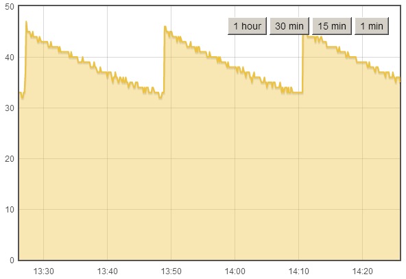
The Python script logs the data to EmonCMS and here’s a graph of how that looks like, the Moteino reports the distance to the water surface, so the spikes means the sump pump just kicked ON, and as water rises the distance decreases until the pump starts again:
EmonCMS_SumpPump

It’s been a rainy spring so far here and I knew my pump kicks ON quite often, now I can see it in real time, and setup alerts if the water rises too much. Seems like the pump is always pumping water out when it rises to 32cm below basement surface. So setting an alert to something like 20cm below surface should be enough since I don’t expect the water to ever rise so much as long as the pump works. The alert code will send me a SMS message when this happens, here’s a test level, I set the live value at 20cm:

Moteino_HC-SR04_SumpPumpAlert_SMS

You can of course setup other types of alerts – like audio alerts or maybe a LED visual indicator (less useful when you’re not in your basement).

Fun/Scary fact: The sensor is very accurate even though there’s a variance of 1cm between some readings (resulting in a sawtooth graph) as water rises. Based on the graphs, how often the water is pumped (every ~23 minutes), and how big the reservoir is, I figured my sump pump removes roughly about 18.5 liters every cycle, or about 1158 liters (306 gal) every day, wow!

So now there’s an extra level of peace of mind when I leave on vacation. I guess being gone for even 1 day could mean disaster if the sump pump breaks down at the same time!

Time to think about how to gather/store all that water instead of throwing it away, after all, I pay something like $11 for every 1000 gallons of city water.

Source code is on GitHub: https://github.com/LowPowerLab/SumpPumpAlert

Moteino Leo: Atmega32u4 based Moteino

MoteinoLeo_R1

I’ve been working on a Atmega32u4 version of Moteino, one that would allow USB connectivity and inherently no need for a FTDI adapter. This is basically an Arduino Leonardo clone that adds the RFM12B radio and a SPI FLASH footprint for optional data logging ability. I meant to post the details of this for several weeks but never found the time for a write-up.

MoteinoLeo_TOP

I now have a working prototype. I have some small changes in mind but it is functional as is. For this version I had to make a small change to the Caterina bootloader to make the onboard LED work properly. By default the Caterina bootloader assumes the LED is sinking current from VDD to the output pin, my version was sinking current from the output pin to GND. This is one of my planned changes, to allow the default Caterina to work with MoteinoLeo out of the box. Wireless programming will not yet work on Moteino Leo and I don’t know when I will find the time to customize Caterina for this purpose. From all I know Caterina takes about ~4kb of bootloader space which might be too much to add ~500 bytes of extra code. I will have to experiment with this sometime in the future if people actually have an interest in this.

Fun fact: using the same DIY metal stencil technique I was able to make a stencil, apply the paste with it and make this Moteino Leo prototype.

 MoteinoLeo_R1_stencil DSC02551_banner DSC02552

Eagle files and bootloader source are published in GitHub.

ATX-Raspi: smart power controller for RaspberryPi

UPDATE: please see this page for the latest revision details.

I’ve posted details about one of my last projects that I’ve been working on.

ATXRaspi is a smart power controller for RaspberryPi or similar embedded systems running form a 5V input. It allows you to have an external shutdown button to turn off your target system without a need to login or to issue manual shutdown/sudo halt commands. I needed this so I could power off my Pi without having to log in all the time. I wanted a physical button to shutdown/turn off my RaspberryPi.

Also now available in the shop, pre-assembled or as a DIY kit.

DSC02674_ATXRaspiATXRaspi_wiring_to_RaspberryPi

Moteino wireless programming source code

I managed to put together a library and refactor the code that I used to achieve Moteino wireless programming.

There’s a new WirelessHEX file in the SPIFlash library. There are new WirelessHEX classes for RFM12B and RFM69W/HW transceivers. These files contain helper code that handles the new sketch over-the-air transmission for both the transmitting and receiving ends. It will increase your sketch size by a few KB, that is just an unavoidable tradeoff.

The target node that is to be wirelessly reprogrammed will need to have code to listen for a potential new sketch. I uploaded the example sketch along with everything else to the RFM12B library examples.

The gateway node sketch, target node sketch, python script that passes the HEX file to gateway node are all located here: 

https://github.com/LowPowerLab/WirelessProgramming

The custom DualOptiboot bootloader allowing the reflashing with the sketch stored on the external SPI FLASH memory chip is here: https://github.com/LowPowerLab/DualOptiboot
I managed to keep the size just under 1k. So in the future Moteinos will probably ship All Moteinos (R2 and R3) are now shipping with this bootloader to allow for potential wireless reprogramming if you also have the FLASH chip onboard the target mote.

I would call this an alpha release even though it works pretty well. Sometimes it’s a hit or miss because of the delays I’ve set in python. Those could be refactored and code improved to be smarter about initial requests for a sketch transmission. But it seems in most cases it works the first try.

Further improvements are:

  • increase speed of transmission
  • test with larger sketches
  • refactor python script, WirelessHEX library and gateway/target node sketches

I’ll try to keep up with changes and updates. Right now I have no idea if anyone will find this useful or not.

SPIFlash memory library for Arduino/Moteino

I posted the SPIFlash library I was talking about in previous posts. I have not found a convenient library for that purpose hence this library written by myself.

Get it at my Github repository: http://github.com/LowPowerLab/SPIFlash
Also added a basic usage example under the library.

The All-About-Moteino page describes how you can add a flash chip to your Moteino or even to your Arduino. To access this chip you will need a library such as this one to conveniently read or write bytes to the chip. I would recommend getting used to the chip itself by doing some reading in the datasheet of the chip you are using – there are some particularities as to how these chips work. The library attemps to abstract most of these things so you don’t have to worry about them. At the very least please read the comments in the code for now. Soon I will hopefully add more info and tutorials. Stay tuned for the complete solution code for wireless/in-field programming of Arduino/Moteino using this library. I am working to get all that code organized and posted on this blog.

Wireless programming step 2: SUCCESS!

It works! I was able to reprogram a remote Moteino over the air with a blinky sketch!

Definitely not a ground breaking achievement, but it really felt like “Hello World” all over again! 🙂

I didn’t expect to overcome this so soon but I managed to get past what I thought would be the biggest hurdle: customizing Optiboot for wireless programming. Actually it’s just reading the new flash image from the external flash chip and transferring it into the internal flash memory. The “wireless” part happens in Step 1. Continue reading →

DIY manual SMD pick and place machine for $20

I’ve shot this video over several days a few weeks ago and finally had some time to put it together. Kind of rough cut but I think it proves the point that you can build a very effective pick and place aid tool without spending a fortune. This has already saved me tons of time assembling Moteinos and other SMD projects. I highly recommend something like this as opposed to a tweezers plus microscope/magnifier, it’s very quick and easy to get used to. This tool combined with my home-made SMD metal stencils are a huge improvement over manual solder paste dispensing and hand placing SMD components with tweezers. I also tape the SMD component strips to a piece of cardboard with double sided sticky tape, to avoid having to dump components on the table and then spend time turning and aligning all those that are upside down and in all directions. That also really helps with polarized components.

And a timelapse:

Wireless programming step 1: SUCCESS!

UPDATE: See Step 2 for actual results.

Well, the title may sound somewhat misleading. But read on. After many days/hours of trial and error I was finally able to validate and transmit an intel HEX flash image to a remote Moteino, which stores it on an external SPI flash chip (soldered to the new SPI Flash footprint available on all Moteino R2s). This is the first step towards wireless programming, and probably the easier step.

Moteino_R2_withFlash

I really hate to write bits and pieces of an unfinished solution and keep the readers in suspense/anticipation of what’s coming next (I see there’s a trend for this on some blogs, to increase blog hits and keep users “hooked”), but I think the wireless programming endeavor is rather long and complicated. Yesterday I achieved what I long wanted, to get a new sketch wirelessly transmitted and stored on a remote Moteino, for later interception and reprogramming through a custom bootloader.

For those unfamiliar with a HEX file, it’s the file generated by your Arduino sketch, and then uploaded to your Arduino/Moteino when you click “Upload”. It all happens behind the scenes and through the attached FTDI adapter. It’s a complex protocol that involves a handful of moving parts. The most important is the bootloader which lives on your Arduino/Moteino, which must be able to intercept the “Hey here’s a new program for you!” request and start re-programming the internal flash memory. But for all this you need wires!

Wireless programming of your Arduino/Moteino is useful when you have nodes sitting in trees, on top of your house, in your attic, underwater, underground, inside sealed enclosures, generally where it’s very hard to physically reach once you have a node deployed.

Continue reading →