SwitchMote R2 Kit released

Update: The assembly and user guide for SwitchMote R2 has been drafted and is published here. SwitchMote is now available at the LowPowerLab webshop. The guide for R1 is still available here. Pricing is overall about the same as before, unfortunately the isolated Recom PSU used in the kit is a very pricey component, but people asked for isolation and certified components, so here we are.

SwitchMote R2 coming soon

UPDATE: It is now released (release notes). Assembly & guide is here. Kit available at the shop.


You asked and I’ve listened.
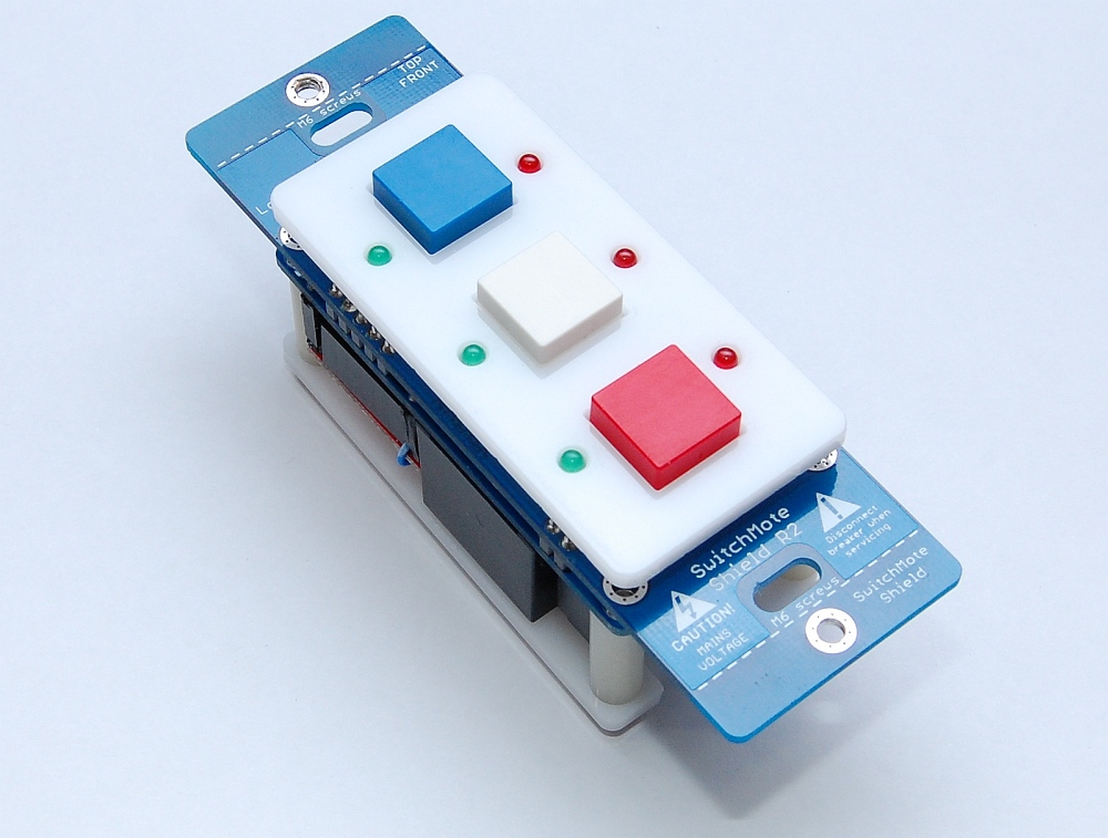
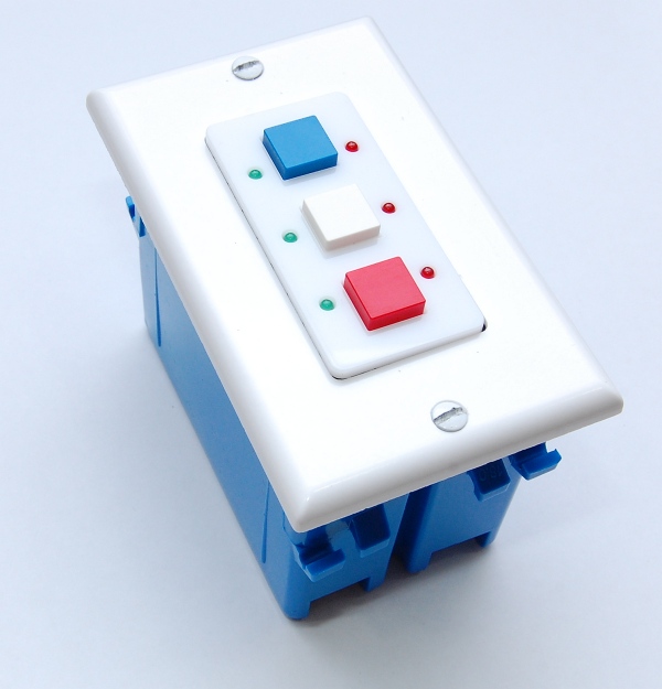
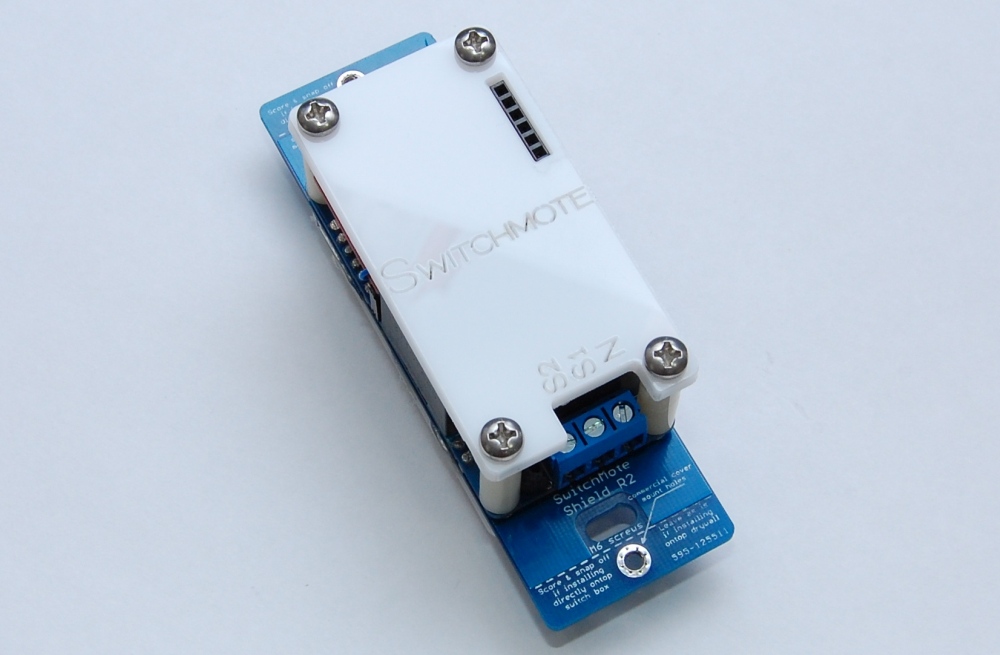
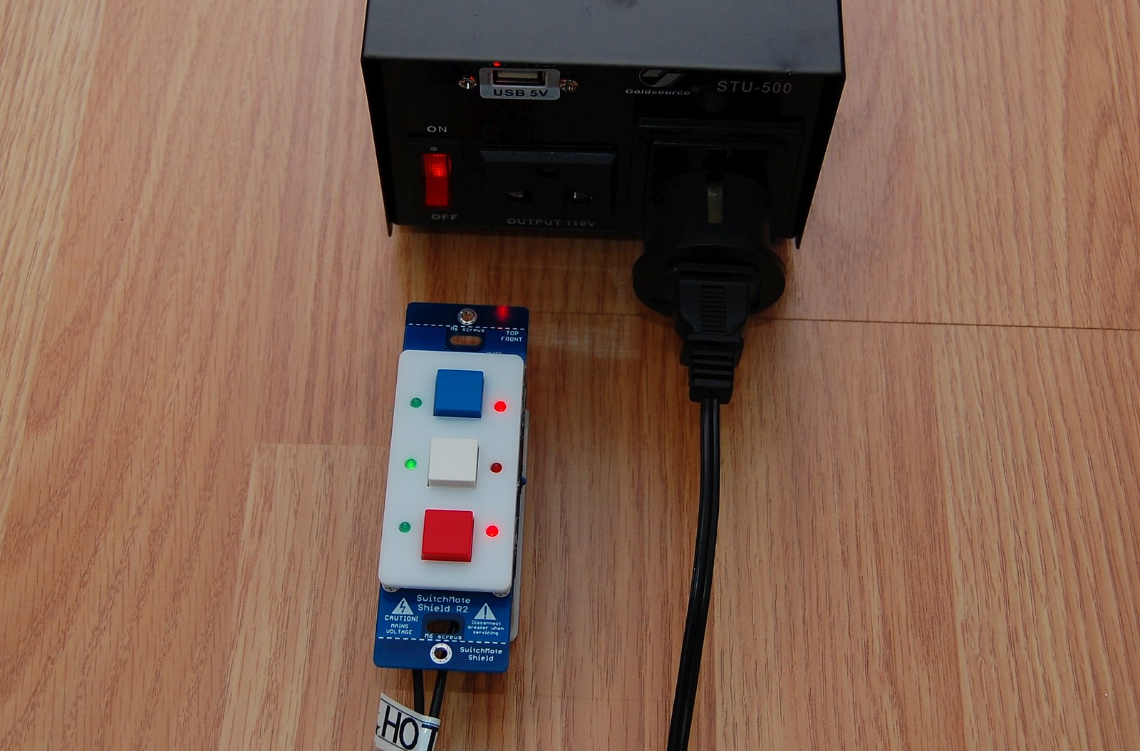
SwitchMote R2 is coming soon as a 100% kit, and should address most safety concerns and shortcomings of R1. I gave up the previous non-isolated design because of different considerations. The switching regulator was not able to work reliably beyond 185V from a half wave rectified input. Then lots of people talked about isolation and supporting loads higher than the 100W on R1. Well I came up with a design that is only slightly bulkier, and is fully isolated (3kV) through a UL certified PSU that supplies 5V @ 400mA for the electronics, uses a very compact coil relay with up to 5A @ 250V load. The design is also much more balanced and I’m happy with the result, the back cover plate uses 4 mounting spacers+screws, allows programming through the FTDI female connector. You can solder your wires directly to the PCB if you are required or you can use the traditional screw terminal. And lots more to talk about but more details will be included in the assembly and usage guide. And yes it works at 240V, doing timed testing right now:

The non-isolation part was of concern because of liability and because I am not a huge company to back it up. To prove my point, look at the tear-down photos of this IRIS switch, it uses a non-isolated design, will you buy it? Continue reading →

Laser cut case for RaspberryPi gateway

Since I imported my new laser cutter from China I wanted to give my RaspberryPi gateway setup a facelift and organize it in a nice custom case which I can actually show off to friends. Before we move on into the details, here’s a perfect spot for a BEFORE/AFTER shot:

This post will describe how I built this case and will include the source files that you can use to customize your own case based on these blueprints. Continue reading →

PowerShield R2 released

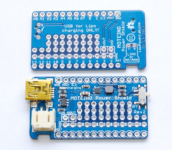
Due to some intermittent voltage drop issues on the first revision of PowerShield I refactored the design and released a new PowerShield R2 based on the LTC3525 fixed 5V booster that should address this issue. This is a much more expensive chip than the TPS61220, others have used the Linear Technology boosters with success so hopefully it’s more reliable, but price will reflect this. It also means there is no switching between 3.3V and 5V output any more. For 3.3V projects, a Lipo can be connected directly to Moteino and the onboard regulator will provide up to 250mA of current to the Moteino itself and any other peripherals attached. There are also some other changes, notably the charging current has been set to 212mA (4.7K PROG resistor on the MCP73831), down from 500mA (2K PROG). The battery connector has been rotated 90 degrees and a notch underneath it was added to allow the wires to be flush to the enclosure sidewall. The rotation was done to allow the USB charging side to be inserted in the wall of an enclosure without the wires interfering with that. This should be ideal for MotionMotes or similar projects where a PowerShield+small Lipo are used instead of a 9V battery. Then the MotionMote could be plugged in and recharged whenever it runs out of juice, without opening the box. Continue reading →

Moteino MEGA prototype

UPDATE: The issues are now resolved. See this post for updates.

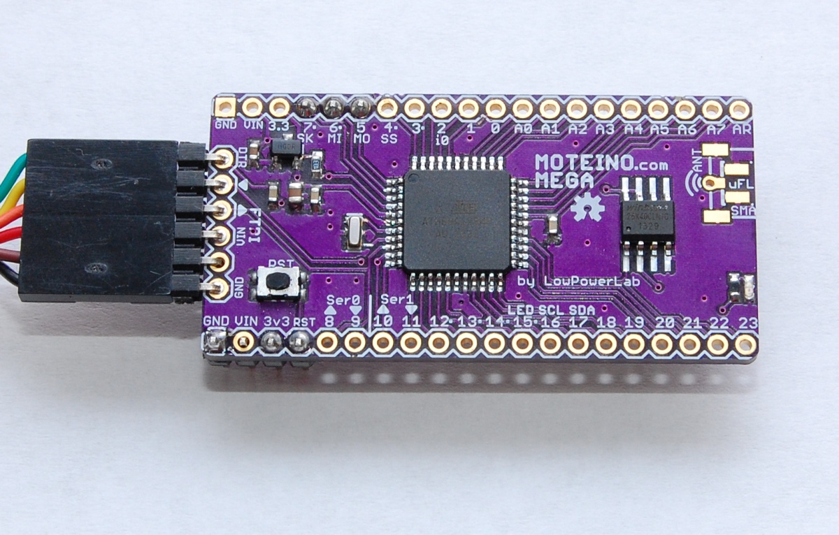
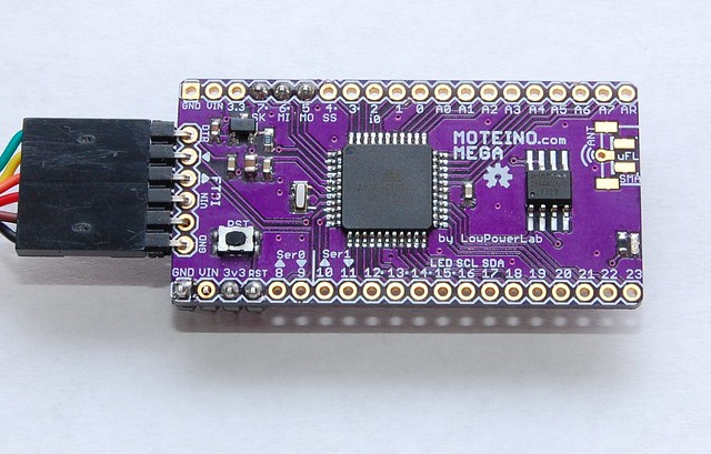
Hello folks. I’ve been trying to develop a new Moteino variant, one based on the ATmega1284P chip. I dubbed it Moteino MEGA since it has significantly more memory, IO and functionality than the 328P. All went well except when trying out with RFM69 radios, I can only transmit but not receive. So I’m writing this post in hope that someone else tried the RFM69 library with an Atmega1284P and has some tips to spare. I’ve been using the maniac-bug 1284p arduino core and from all I can tell the external interrupts are set correctly in this distribution. I used my Node sample sketch with appropriate RFM69 settings. The receiver is a regular Moteino. The Moteino MEGA is calling sendWithRetry(…) which sends the packet 3 times until it gives up. All three packets are received at the gateway, and all 3 ACKs are sent back. I modified the RFM69 lib to attach the interrupt routine to INT2 if it’s a mega1284p. But the interruptHandler() in the library does not trigger on the Moteino MEGA. I pulled the logic analyzer and it looks like the INT2 (D2, wired to RFM9’s DIO0) goes HIGH when it’s expected (and stays HIGH quite long, weird), but the interrupt routine is not called. That’s where I’m stuck. At this point I’m not sure where the issue is but I tried a simple interrupt handler program which seems to trigger just fine:

boolean interrupt = false;
void blink()
{
  interrupt = true;
}

void setup()
{
  pinMode(LED, OUTPUT); //LED=15
  attachInterrupt(2,blink,RISING);
  Serial.begin(115200);
}

void loop()
{
  if (interrupt)
  {
    Serial.print("X");
    for (byte i=0; i<10; i++)
    {
      digitalWrite(LED, HIGH);
      delay(25);
      digitalWrite(LED, LOW);
      delay(25);
    }
    interrupt = false;
  }
  
  digitalWrite(LED, HIGH);
  delay(500);
  digitalWrite(LED, LOW);
  delay(500);
}

I hope to get past this hurdle and be able to release this new board since some people asked for more memory and IO. I have yet to port DualOptiboot to it but I need to solve this mistery first. Maybe there’s a bug in the 1284P core. Or something I’m omitting, just out of ideas right now. If anyone has an idea why this is happening please let me know. Thanks!

UPDATE: I tried an RFM12B with the atmega1284P and the good news is it works with my RFM12B library. The bad news is that after about 15 minutes of running the sample send sketch it stops working and the atmega1284p appears to be completely nonresponsive, even to the AVR programmer. I’ve tried this with 2 chips, both died after about 10-15 minutes of continuous transmission. So I’m baffled. The power supply is the same as the regular Moteino – 3.3V and nothing heats up, radios wired the same except to INT2 instead of INT0, same 16mhz resonator. Chips were from digikey so I don’t think they are counterfeits. Any hints anyone?

Importing a laser cutter from China

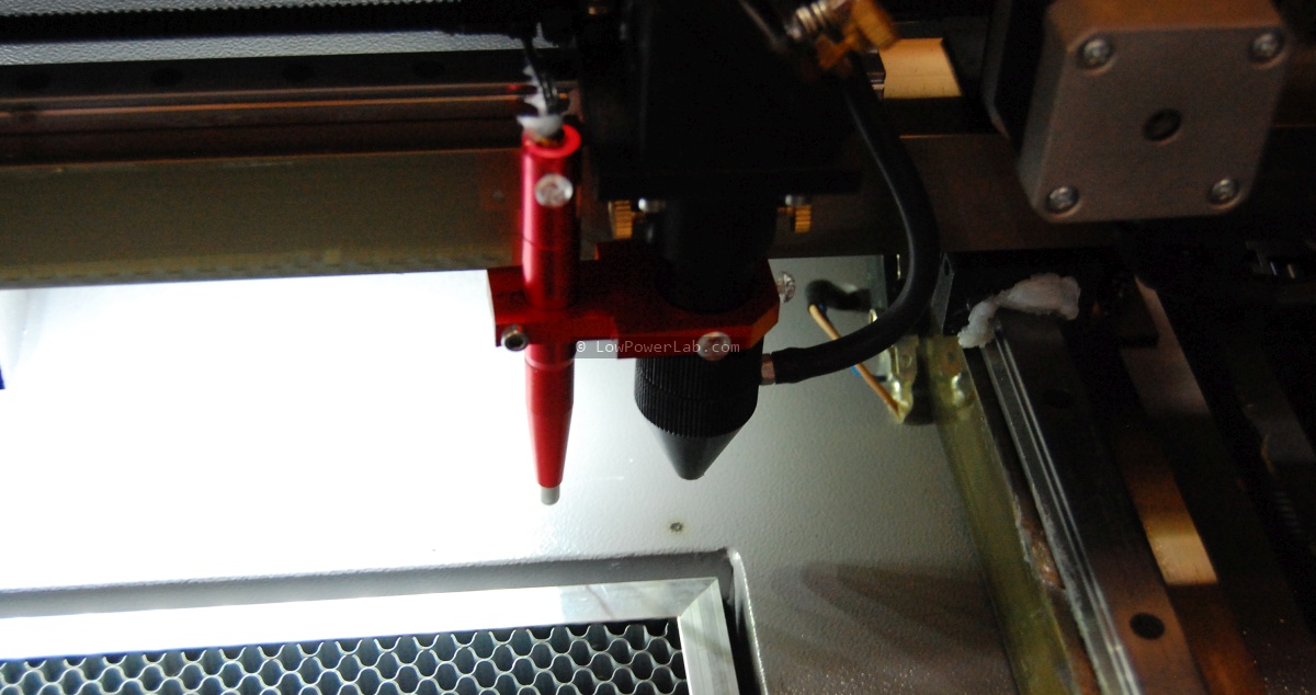
As a break from the pick and place posts, in this article I’d like to aggregate my research about laser cutters and my experience importing a chinese laser cutter. There’s a wealth of knowledge scattered around the web, and this article won’t meet everyone’s search criteria, but hopefully this will be a resourceful stop for those that are in the search for a similar machine on a budget that can achieve the same results as a high end laser cutter/engraver.

I’ve been laser cutting my stuff at Techshop Detroit for a while since as an instructor I had free access to their shop and CO2 Epilog Helix lasers. That was cool but I didn’t have class very often and often when I had an immediate need to cut/engrave on the laser I would have to burn the gas and time to get there, about a 30 mile/35 minute drive (no traffic). Also I had to make sure to schedule well in advance to reserve a spot. And to top it off, they had a major ventilation issue for several months so cutting acrylic was restricted to 1 hour, not nearly enough to do what I needed. A single 24×18″ panel full of SwitchMote covers would take 45 minutes just to cut. Not counting setup, adjusting the machine, making sure it’s clean and ready to go, testing a few cuts on scrap, etc. In short, this was not scaling very well.

So I decided to look for a  better alternative, knowing my laser engraving needs would only grow. The common denominator answer was to get my own CO2 laser cutter! Yikes, both exciting and scary thought. Exciting because it would solve all the issues I mentioned and save me tons of time, scary because it’s a big thing to haul around, noisy, hazardous, dangerous if mishandled, requires ventilation, maintenance, liability, etc. Doh…

Anyway, so what were the options? Continue reading →

Pick and place – entry level options

Startups that manufacture electronics are faced with a limited set of choices when it comes to getting their hardware assembled. Each of the methods below have an array of possible approaches, some good some less so. I will try to cover what I’ve seen in my quest, hoping this will be a good overview of what’s out there. If I miss details or interesting methods please let me know and I will keep this list updated. This is part one, where I look at options of assembly without getting into a real commercial pick and place.

Doing it manually. Everybody started here, including Adafruit, Sparkfun and others. It’s great and fun at first and you learn a lot about surface mount technology (SMT) and also gain respect for how hard quality assembly really is. And we’ve seen countless ways people do this around the world. Some spread paste with a toothpick or dispense with a DIY syringe, then place parts with tweezers. This works for about 5 minutes before you go crazy, especially if you go smaller than 0603. Others laser cut mylar stencils to speed up the paste deposition. I etch my own stencils from soda can aluminum, this is fast and works great. For placement I’ve seen people make some fancy ball bearing jigs to help them move their hand, a bit better.

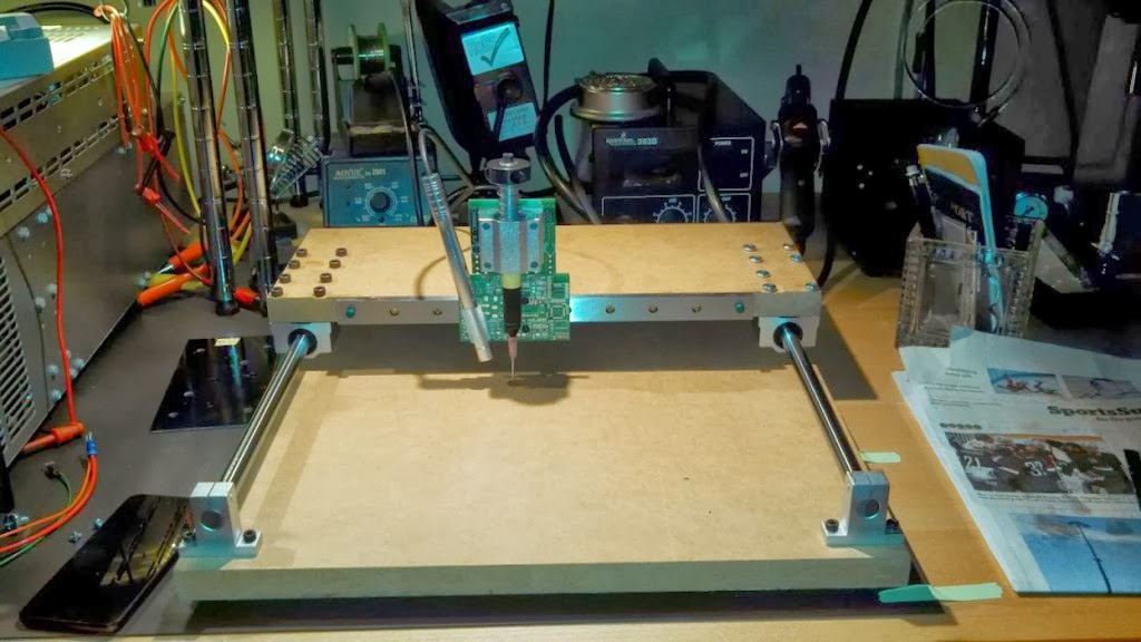
This is very cool and I almost did this myself but I think it’s overkill and a bit slow and … more expensive than it needs to be for what it does, but I can appreciate the effort of its creator. One advantage of this fixture is the ability to better hover over larger PCBs while placing. FWIW the maker even went as far as mounting a camera to help placing the parts, a nice touch, but looking at his video of it in progress the angle of the camera looks weird and looking away on a monitor when you work with your hands is what cuts the speed. Here’s another one of the same kind for reference. I do the same as these, only probably faster, with my aquarium pump pick and place (hold your laugh for a moment there) which cost me about $20 in parts, took about 30 minutes to make, and has full stereo vision – my eyes, can’t beat that for the price. I like to brag about this method not because I’m using it, but because it’s probably the best 100% manual method I’ve seen. Why you ask? I can do up to 7-800 CPH (measured!) with it on less complex boards. The only downside is obviously having to sit there all the time, with some neck and back strain, and the part alignment is less than ideal, but paste reflow really helps. I’ve assembled many thousands of PCBs this way, it works nicely and gets stuff done, but it’s not great. I wish I spent all that time developing new projects. So what is better than this?

Continue reading →

PCB trivia – can you spot the short?

Ah the joys of manufacturing …

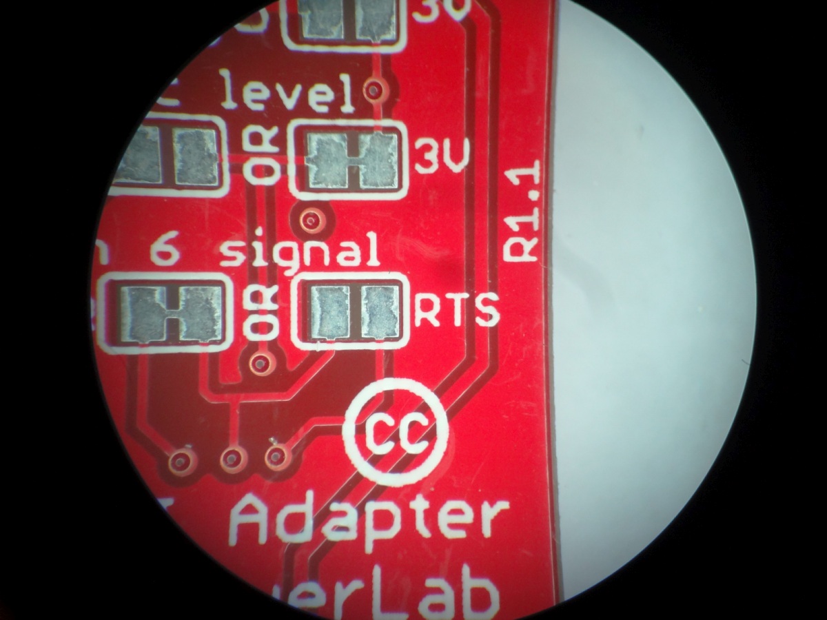
This one drove me crazy, no short at a close inspection. But I was determined to find it. I ended up desoldering almost all components off thinking the short is under some cap or resistor, but the short was still there. I had to pull the microscope to track it down. Here’s a shot of the PCB through the scope. Can you spot the short?

Shop now running on SSL

So far my site did not have a SSL certificate, mostly because it was not needed. Some people were concerned that their data is not secure when they check out at the webshop. That is partially true. The reason is that the financial stuff is done over at Paypal and the shop only captures the name and shipping information, not credit card numbers. If a very bored to death hacker is interested in intercepting and stealing one customer’s name and address at a time on my no-name site instead of just heading over at target.com and stealing 400 million credit card numbers and transaction info all in one shot, then that could be a concern.

So anyway, to make everyone happy, I spent the $ and time to get this setup. Let’s hope my host did this right and there won’t be more down time. SSL is now for real and the shop should show as HTTPS, you should see this when you go there dear customer:

HTTPS

Happy secure shopping, and don’t forget to smile, every day is a blessing.

PPM visit and Quad IVc/4000c pick and place demo

In an effort to deliver truly meaningful and comprehensive content, I will write a few articles about pick and place machines and SMT assembly, after many months of trial and error with various methods, in hope to help others who may want/need to get into SMT equipment and assembly. The focus will be on pick and place machines, my observations, what I learned in my prolonged research into pick and place machines over the last year, what some people say, what some companies end up choosing and why, what to look for, what to run away from, etc.

I first saw the article about the Quad IVc pick and place on Ohararp.com and was curious to see this machine up close.

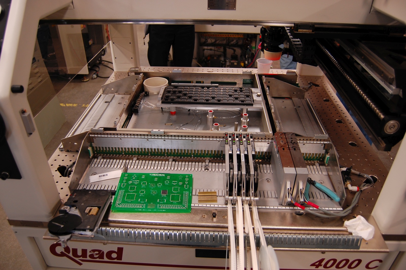
We visited PPM (Precision Placement Machines) some time ago and was able capture a few of the cool things we’ve seen there. This video shows a demo run and feeder setup on a Quad 4000c (Quad IVc upgraded to Windows 7).

I really took a long look at this machine and that’s why I took a day off to go out there (they are truly out in the country). Unfortunately there aren’t many resources on the web about these machines, at least not high quality pictures or videos, so I hope this will change that at least a little bit. The visit was very much worth it and the great staff showed us around and throughout the PPM facility. There’s too much to say about the visit and I hope to make some time to post more pictures later so here are a few more photos of the tour. Later I will expand on our observations on the Quad pick and place.

For now I will just post this video showing the Quad 4000c in action. It illustrates how the machine dispenses paste, places a range of components and finally how a feeder is setup: