Making a custom RaspberryPi case

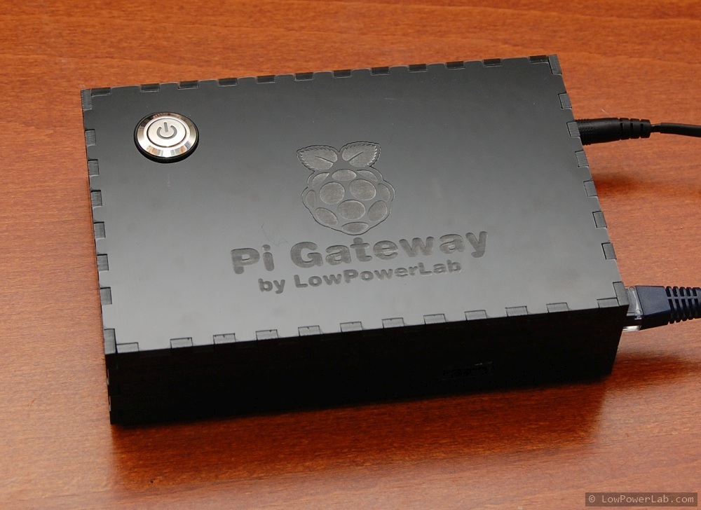
Bulk made enclosures are useful when you just want basic underwear on your Pi but what if you need to put something else in there and it won’t fit? I’ve built a Pi enclosure for my home automation gateway before but it was just 3 layers of acrylic to hold everything together, turned out nice. In this post I will show another example enclosure for a Pi gateway.

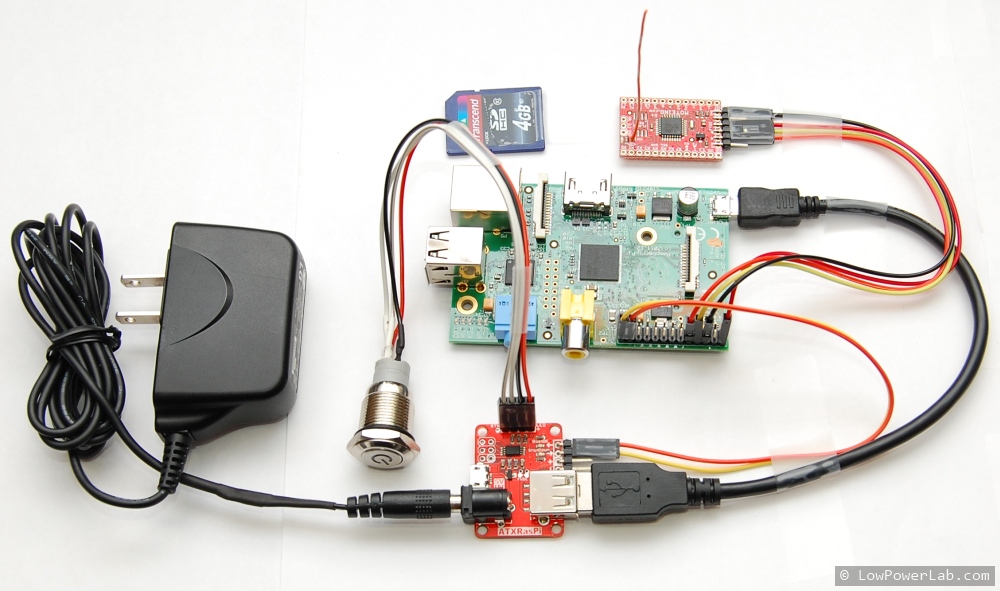
I am finishing up a separate project where I needed to put a Pi gateway in an elegant enclosure along with an ATXRaspi+power button, and a Moteino. This guide can be used as a guide to build a RaspberryPi+ATXRaspi+Moteino setup that can all live together in a nice box to serve as an internet gateway to your Moteino or other wireless Internet Of Things network.

I will show you how I made the case and the steps I took to avoid wasting material while adjusting the cutouts. I will include the corel and DXF files that I used to lasercut the case. I have a 60W laser cutter imported from china, and that makes for a very nice prototyping tool to cut and engrave the boxes, but they are becoming widely available at hacker spaces and workshops all around.

First let’s see what components go in the box: Continue reading →

GarageMote R2 released

Happy new year folks!
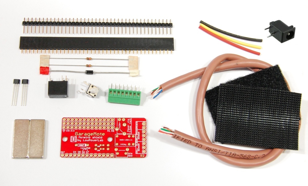
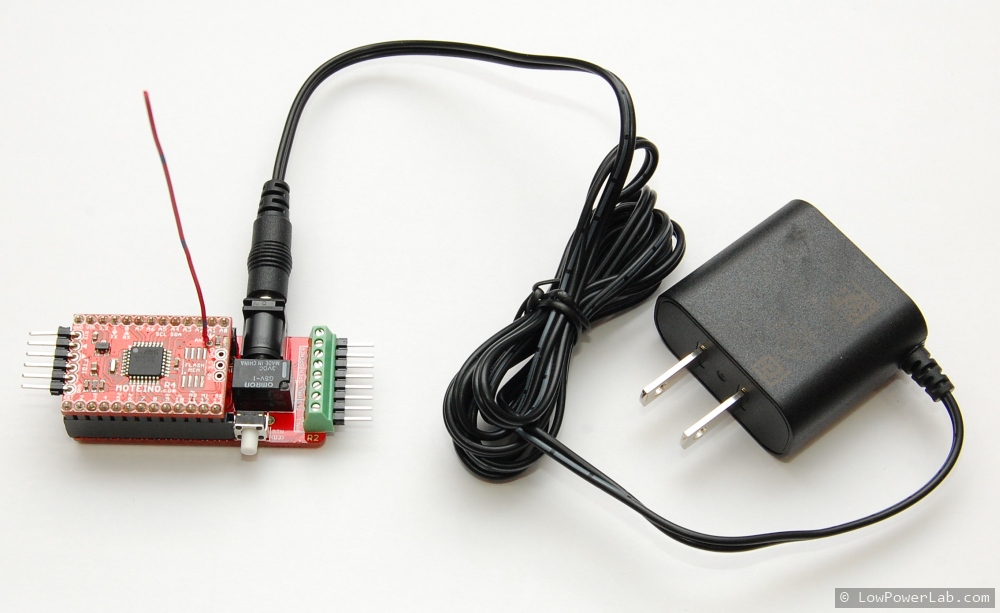
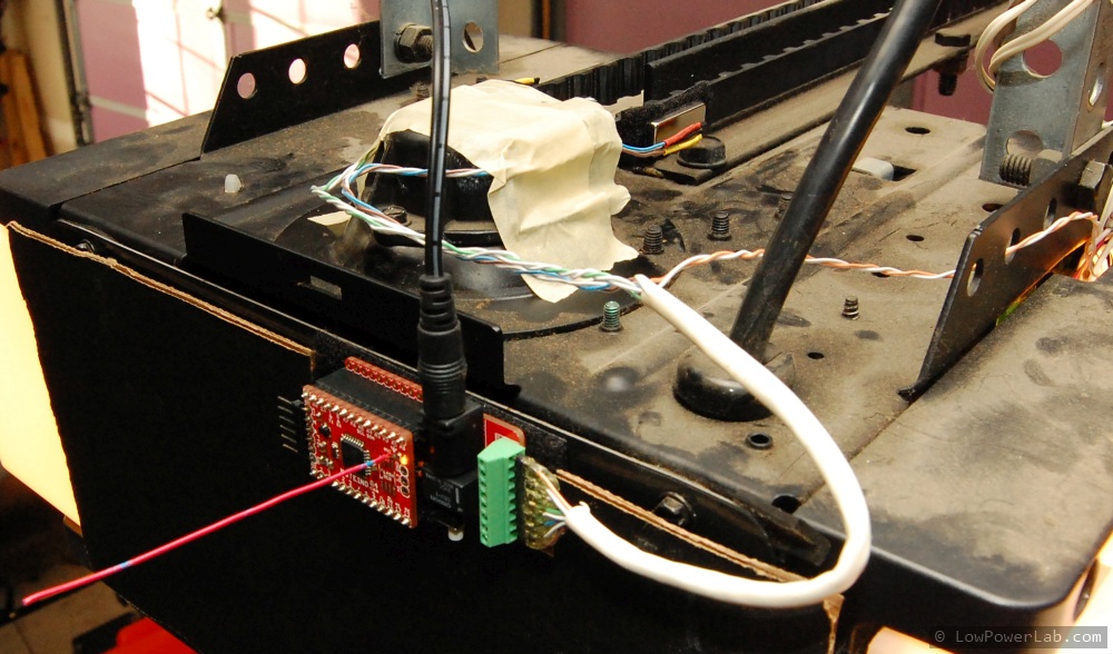
The blog has been silent for a good while. For now I will just announce the new R2 revision of GarageMote and hope to catch up later. Here’s what this new revision consists of, and a few photos to show it assembled/installed:

It is mostly the same as before, but it includes the following new or changed features:

  • R2 kit comes with new unipolar hall effect magnetic sensors; the pinout is the same but these sensors can detect both north/south poles of a magnet, hence easier to install without having to orient the magnet a certain way for detection.
  • R2 kit includes magnets (rectangular ); these are better than round magnets that I’ve personally used before. My opener belt stopping point is a little variable so the length of the magnet helps keep the fixed sensor “in range” to avoid the sensor missing the magnet and trigger an UNKNOWN status.
  • R2 kit includes a 1×8 screw terminal for easy mating with the provided cat5 cable
  • R2 kit includes a momentary button between GND and D3 – no code released for this (yet) but this can  be used to add a function to your GarageMote – like SYNC-ing with a SwitchMote so you can open/close your garage from a SwitchMote button, how cool is that!
  • new 2.1 barrel jack for optionally powering the unit from an external 2.1mm jack power supply, commonly available on ebay or at major online electronics retailers

You can find the new kit in the online webshop. The assembly/programming/usage is published here.

Moteino now on CodeBender.cc!


IMPORTANT NOTE: unfortunately codebender announced they are shutting down on or after Oct. 20, 2016. Hence forth this page is only kept for reference and it will eventually be removed. The codebender programming instances below might become inactive, display an error or show a blank space once codebender shuts down these services. You are encouraged to start programming or move your code in the Arduino IDE.


This is really awesome news!
The guys at codebender.cc have done a great job creating an online place to create, edit, store, share your Arduino sketches. It’s very easy to install and use right in your browser!

UPDATE: Check the new Moteino Programming Guide.

And now Moteino has been added to their fleet of supported devices, along with the RFM69, SPIFlash libraries. Once your Moteino is connected to your computer, you can edit your sketch, or load the example(s) of the many integrated libraries (like the Node example in the RFM69 library) edit the settings to match your hardware and upload it to your board. Another awesome feature of codebender is embeddable sketches, that’s right, any sketch can be embedded in another web page, like the Node example below, you can upload it right from this blog post (see below for browser plugin requirements, or check this getting started guide):

To be able to use CodeBender you will need to create an account, then install a browser plugin that allows access to your computer’s serial ports, which in turn make it possible to reset and upload sketches to your Moteinos (or whatever other board you may have and they support). Also you need to choose your target board, protocol (USBtinyISP for Moteino) and serial port it’s attached to, then click “Run on Arduino” and that will compile/upload the sketch. That’s about it. Please check their getting started guide as well.

I warmly recommend using CodeBender with Moteinos since it’s easy and much nicer than the clunky Arduino IDE, and it’s probably going to get even better as they add more features. Plus I will work with them to ensure the libraries are in sync with the latest releases, and new examples will also be posted on CodeBender. Of course, you can always add your own sketches to your CodeBender repository, just like you did in Arduino, or you can clone an example and load your own settings and modify the code as you like. I will probably start using embedded sketches whenever I want to share code since it allows CodeBender users to upload it right from this blog rather than going to GitHub, copy pasting, making sure they got all the latest updated libraries, etc.

To celebrate this great milestone I am reducing the pricing on all Moteinos by $2, a saving of 10-15% depending on your options, to last through the end of December!

Happy CodeBending!

November 2014 Updates

Here are some updates and announcements for this month.

  • I released important patches to the RFM69 and WirelessProgramming libraries. Please get latest, these should be addressing some network hanging issues in high traffic/congested networks, and also fix channel shifting for wireless programming. The discussion around this patch is documented in this forum thread. As always, I welcome and encourage constructive dialog and collaboration to fix bugs and improve libraries and examples.
  • I am discontinuing the offering of RFM12B transceivers which are getting old and almost nobody is interested in buying them anymore. I encourage the use of RFM69 transceivers for all new projects and upgrades. Moteinos will continue to have the footprint for soldering of RFM12B transceivers until further notice, so those who want to source their RFM12Bs from another source are welcome to use them on Moteino.
  • There were a bunch of recent posts in the forum complaining about issues with FTDI drivers and or inability to upload code to MoteinoUSBs. Some users have returned their Moteinos but in all cases so far I found the boards completely functional which leads me to believe there is a driver issue on some/all operating systems. I was not able to reproduce any of the issues in several Arduino IDE versions. The driver I have today on Win7x64 is FTDI driver v2.12.0.0 updated via Windows Update.
  • There is a new Moteino core that is very light compared to the previous version. This core contains the definition variants for MoteinoMEGA and the regular Moteino. Once you install this core in your Arduino {Sketches}\hardware folder you will now see two new entries in the Tools>Boards menu (restart required): MoteinoMEGA and Moteino. The new officially suported Arduino version is v1.0.6 (stable). Here are the new options:
    Boards_MoteinoUpload_moteinoUpload_moteinoMEGA
  • Moteino and LowPowerLab libraries will soon be integrated at codebender.cc which is a great website based alternative to the Arduino IDE for developing and storing your sketches while enjoying updated libraries and a multitude of other vendor sketches and repositories. It’s very easy to upload your sketch to your board directly from the browser. More on that soon.
  • I am continuing to migrate my PCB designs to ENIG finish which is more costly to manufacture but is lead-free and makes for better and more professional looks of my designs. I hope my customers enjoy and appreciate the better quality at the same low prices.
  • modelrailroadYou can see a cool model railroad project involving Moteino starting at page #92 in this November-2014 edition of Model Railroad Hobbyist Magazine (courtesy of Geoff Bunza). He also posted a well documented tutorial of how to get started with Arduino Mini or Moteino at page #99 in the same edition. Youtube video of the model in action is here.
  • The Moteino-Framework did not make it into the finals of the 2014 Hackaday Prize contest, but it did make it into the top-50 semifinalists out of ~800, and is on place #13 of the semifinalists listing according to community vote ranking at the time of this writing. I felt there was no chance it would make it in top 5 since automation is boring these days (despite the innovations in my entry), and in the end none of the other similar entries made it either. Honestly I was a bit disappointed with the grand prize winner project, I think it’s a cool project but as far as usefulness for the masses of DIYers/hackers I don’t find it very interesting, or maybe I’m the only ignoramus not really interested in launching satellites and depending on people I don’t know to supply me data about my satellite when it flies over their location. But I guess usefulness was not among the judging criteria.
  • As a result of making the top-50 for the Hackaday Prize (semifinalist) I won a $1000 which will be awarded as a mouser.com credit. I think that’s way better than $1000 worth of uninteresting swag picked by the Hackaday sponsor/staff on the winners behalf. How should I spend this prize? I want to get something memorable like a tool, so I remember I won this prize when I use it. Any suggestions?

Schlage smart door lock hack/teardown

Well it’s not really a teardown, but I did take apart the unit to analyse the electronics, which is the reason I bought this in the first place. Reason #2 was to see if I can hack it to control it via Moteino. Watch the video at the end of the post to see the results.

As the title suggests it’s a smart door lock with a for coded entry and is based on “Iris” which in turn uses ZWave RF wireless technology (made by Zensys), a closed source patented protocol+hardware stack that is OEM-able to automation system makers who want an “off-the-shelf” wireless stack to integrate into their product.
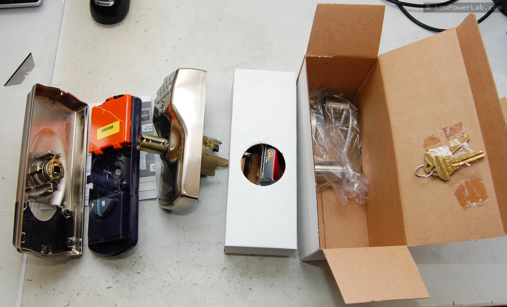
Here are some unboxing photos:

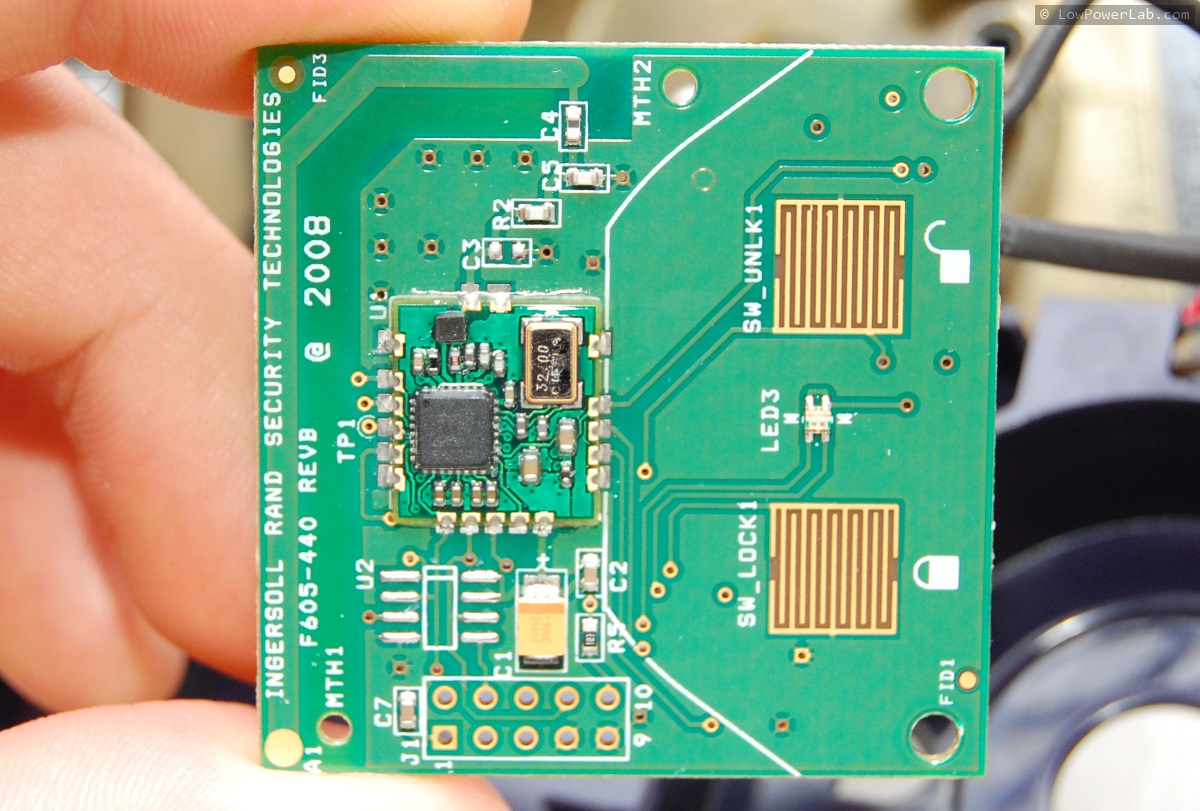
The mechanical side sits on the outside and also contains the keypad. I was eager to open this part up and I was met with a MSP430 controller that drives the keypad along with some circuitry to drive a small DC motor which turns a very small spring which in turn engages a latch. It was very difficult to put it back together and there’s not much going on in there anyway. The brains of this unit is a Zwave SOC (system on chip) which is similar in looks to the RFM69 transceiver. It’s soldered on another host PCB which has two button pads for LOCK/UNLOCK action from the inside of the house, and a red-green LED for visual feedback. The ZWave unit is a MCU+transceiver SOC with similar specs to the Atmega328 and works in the 915mhz unlicensed band in the US.

There are a few interesting finds on this PCB:

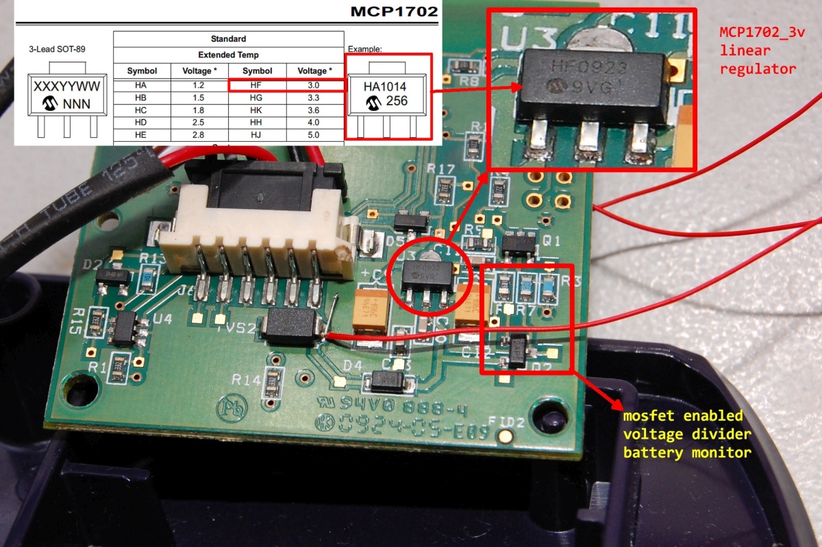
  • Power is provided from the 4xAA 6V battery pack through a voltage regulator. The regulator is a MCP1702-3V linear regulator, the same type that Moteino uses (except Moteino is MCP1703-3.3V and accepts up to 16V max input). This is significant because this proves mass manufactured low power electronics can and do use low dropout linear regulators without a major hit on battery life. Some people are concerned about battery life and email me to ask why I didn’t design Moteino with a switching regulator instead. A lot of reasons that I won’t go into here (except to say a low dropout linear regulator will perform great if your firmware is low power enough). And after this teardown I feel even better about it.
  • There is a mosfet enabled resistor based voltage divider which is obviously a battery monitor. A very simple and cheap alternative to other dedicated battery monitoring chip solutions. The resistors are obviously 1% or better and the divided voltage goes into one of the analog pins of the ZWave SOC.
  • The Zwave front end is probably controlled by the MSP430 controller via a 2 wire (serial?) interface, I would guess a UART. The Zwave SOC has a “patented” protocol API which is how the host application configures and talks to it. That part was not something I spent too much time to investigate since I’m not interested in ZWave.
  • The logic on the ZWave SOC is active low. Meaning that to turn ON a LED the pin wired to it has to be driven LOW instead of HIGH.
  • The ZWave PCB was covered in a clear electrical insulator coating (which scraped away very easily) to shield it from humidity, but nothing else was. This is weird, I can’t imagine why they would weather proof the MCU/radio but not the power supply.

Here are the closeups of the main PCB:

In the following video I show more details about how the unit works, power consumption, where I tapped into the circuit to control it, and how it is controllable via a Moteino/Arduino microcontroller. There is very little space in the case to add any other electronics in there. But the Moteino would probably fit OK. This makes me feel pretty good about my Moteino design decisions – one paramount requirement was small size without sacrificing usability (by tightly spaced non-breadboardable headers or cutting back on exposed pins) – it had to fit in such small places as this door lock.

Motion-OLED-Mote kit released

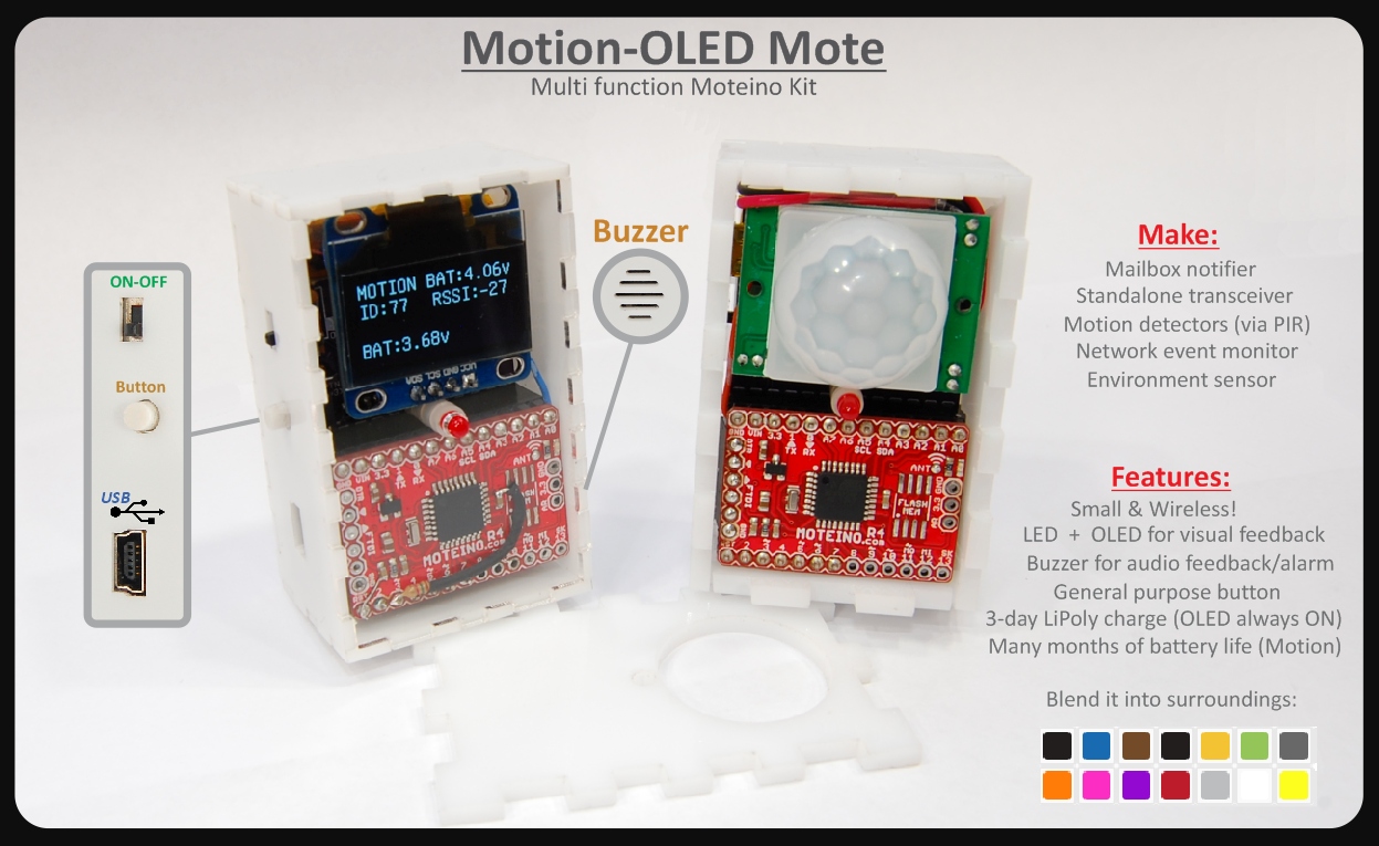
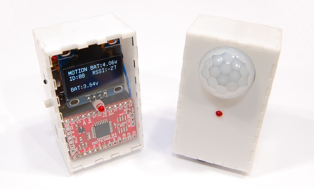
I am pleased to announce the release of the Motion-OLED Mote Kit. It is now available in the webshop. This kit can serve as a wireless motion sensor, mailbox notifier, display monitor for your wireless network. It’s extremely convenient when you just want to see if there is motion somewhere in your house, or if you just want to check your snail mail, without the need of a gateway or anything else – just build a MotionMote and an OLEDMote, keep one where motion needs to be detected and watch the messages coming on the display on the other unit. The onboard buzzer and LED give additional options to indicate visual and audio alerts when an event happens.

The kit contains most of the following components, depending on whether you order a Motion or OLED version. For more details about the assembly, programming, and usage you can visit this dedicated page.

This kit will build either one of these two display or motion-sensor units:

October 2014 updates

Maybe not really obvious but a lot of stuff is going on at the humble Low Power Lab. Let me just throw in some announcements and updates:

  • Moteino R4s, MoteinoMEGAs and ATXRaspis are now coming in ENIG gold finish. This is to move towards more professional looking PCBs and to meet RoHs lead-free status. This costs a bunch more to make but instead of raising prices I actually discounted the Moteino options and will do my best to lower prices even more. I am trying hard to keep Moteino a high quality product at an affordable price for makers and businesses alike.
  • I’ve been busy putting together the requirements for my THP entry. The top 5 finalists will be announced around October 13. If Moteino Framework makes it in the finals that would be quite cool, but would put more stress on me to meet the extra criteria required by end of October.

  • One of the things I’m working on is getting a Motion-OLED shield for Moteino ready for production. Here’s a peek of it:
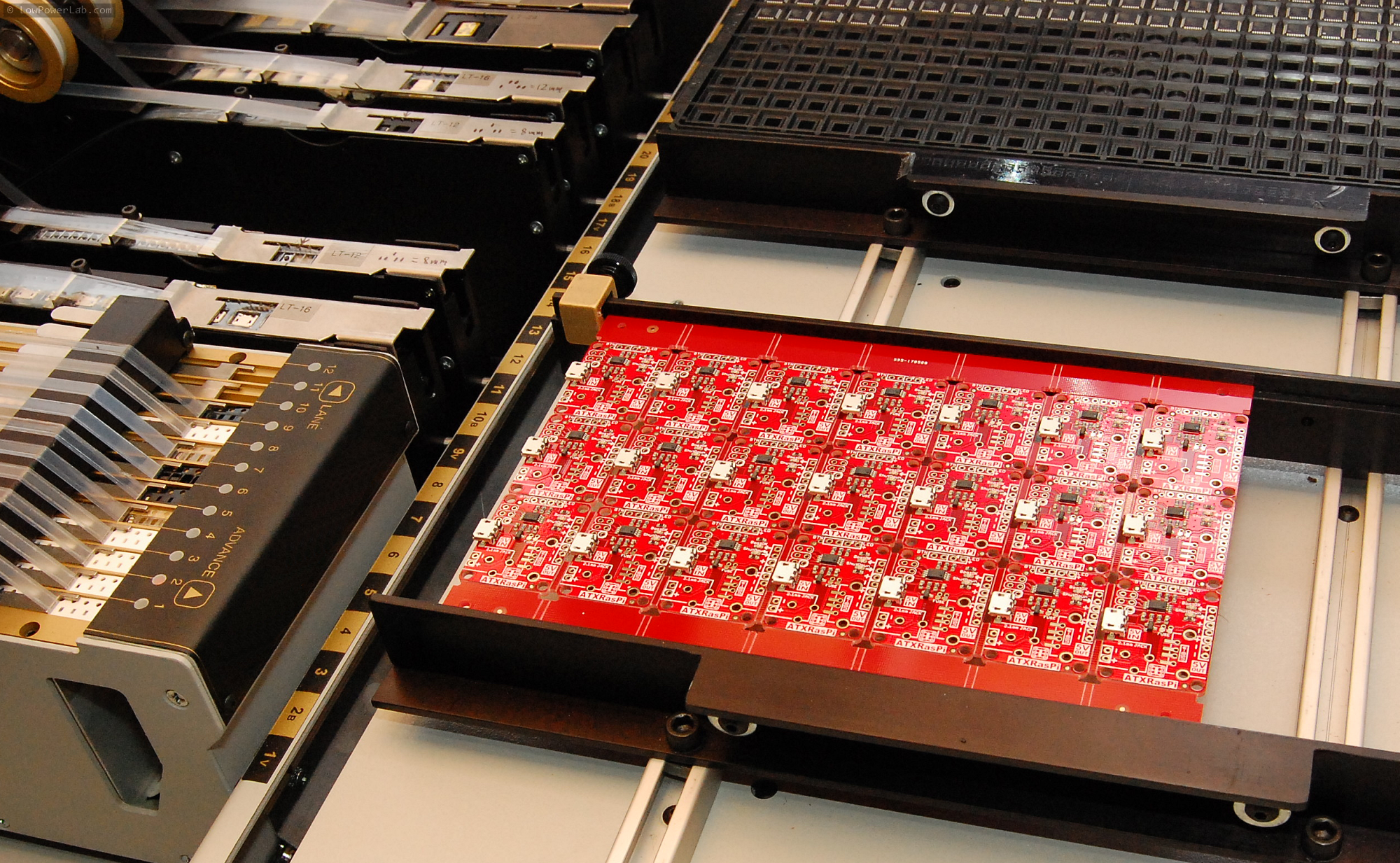
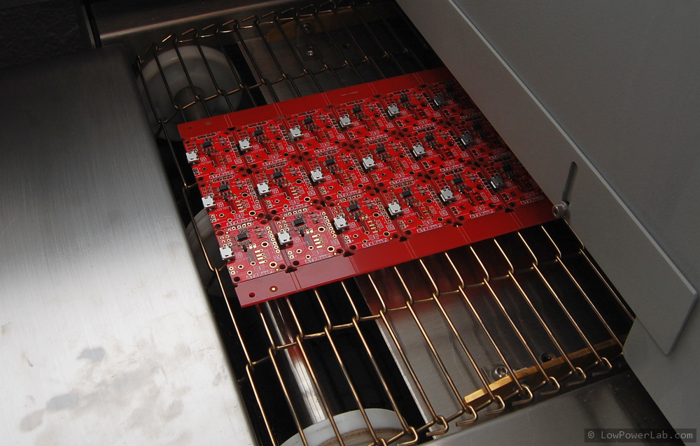
  • I’ve been having a blast with my new pick and place. I am transitioning all my designs to panels and adding fiducials for vision correction. I can’t help but mention that there’s a world of difference between professional machines and “DIY Open Source” type of machine that are just toys. Before getting my assembly equipment, I was doing manual assembly with a $20 modified aquarium pump and reflowing in a slightly enhanced toaster oven. Other than me physically being there I still think my previous methods were better and more productive than a lot of these makeshift pick’n’places.

    Something tells me that people are fascinated with “DIY open source pick and place machines and 3D printers” and other not really “connected” devices which was the main point of the Hackaday Prize contest. I know exactly why we’ve not seen even one such successful Pick’n’Place project, not even close, and my prediction is we will not see one too soon either based on my experience with a real one. I will expand on that more extensively in a future Pick and Place article.

  • There is a new revision of PowerShield, mostly PCB changes and making stuff more obvious to understand and use:

Closing the security gap

HTTP(S) and Websockets Security

There are a lot of open source home automation attempts out there. Many are missing some essential security that leaves them vulnerable. Those that actually allow the user to control physical things in their home are especially vulnerable. An attacker could gain control and cause an appliance to turn on-off repeatedly causing a hazard, could gain access to the home by opening a garage or door, or could just watch for human activity for other evil purposes.

I knew that getting ahead of the crowd meant imposing some strict requirements including physical and virtual security to restrict access only to those authorized and minimize the chance of an attack.

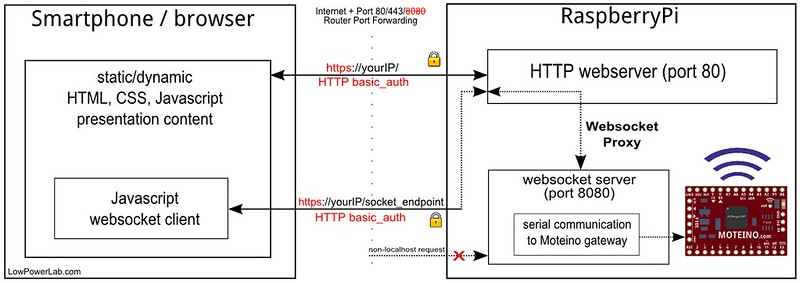
Sure, anyone can add some authentication, not a big deal. And it’s not too hard to add SSL. I had thrown web sockets in the mix for real time updates (cf polling as a method of “updating” on end clients). So web sockets had to be secured as well. Since the node.js websocket server runs on a different port than the webserver, rather than securing two channels of communication (webserver and websockets) I implemented what I believe is the first OSHW home automation interface with real realtime two-way communication between the webserver and the clients, by marshalling the websockets through the webserver itself, and thus obfuscating the internal websocket port. Hence both the webserver and websockets traffic run on the same SSL port 433. The websocket server is obscured and any non localhost requests to it are blocked. The details of this implementation are extensively documented in this article on my blog. HTTP-Auth authentication blocks any intruders from accessing the web interface. Below is a diagram of this whole scheme.

 Wireless Security

Another important aspect of security is obfuscating the wireless requests and making it harder or impossible to decode. This is achieved with hardware AES128 encryption on the wireless transceivers such that any wireless packets to and from the end nodes cannot be decrypted by an attacker.

A more sophisticated attacker armed with a  $20 RTL-SDR dongle and laptop could listen for more extended periods of time and record messages and then replay them in hope to cause a door to open for instance. Such a simple portable SDR solution (cf. portableSDR project) is elegantly explained by Alan (w2aew) in this video:

Hence the remaining gap to fill is implementing an algorithm to thwart any replay attacks for those critical commands that control physical things like appliances, lights, garage, doors, etc. This is essentially a way to salt each wireless packet with a sliding window type signature such that if it’s replayed it would be obsolete. Until this is implemented, one can tune their end node transceivers output power to only be powerful enough to reach the home gateway, which would be recommended anyway to avoid polluting the RF traffic in your neighborhood. So unless you have a curious close-by neighbor with radio knowledge who might eaves drop on your RF traffic, it would make it harder for an external intruder to get physically close to your home/location to record your traffic and try to mess with it via replay attacks.

Rolling​ code vulnerabilities​

It​​ seems a lot of key fob entry systems ​like auto locks and garage openers are using rolling code to secure their wireless communication. The transmitter increments a number in the packet with each subsequent transmission. The receiver remembers the last received token and knows what token or series of tokens are expected next​. This attack involves blocking/jamming legitimate signal, then replaying the intercepted legitimate signal. Because of the jam, the receiver hears the noise and never receives the legitimate signal with the expected new token and thus the replayed message will appear legitimate. Continue reading →
Moteino Framework architecture decisions

My vision for Moteino was to create an affordable/open/ideal/easy hardware platform that would fuel a new generation of wireless internet-of-things, and I think it came out pretty decent. My Hackaday Prize entry even made it in the top 50 semifinalists (out of 800+). More devices are being added to the Moteino Framework and existing ones are being improved to make it fun for those makers who like to DIY and solder their internet-of-things from easy to assemble kits. The end users have maximum freedom as far as using/building stuff with Moteino. They can build absoltely everything from scratch, as some have done, but some prefer to just save time and buy building blocks. Hence I funded my way through this adventure by selling ready made Moteinos and kits in my webshop.

People have asked many times why the Moteino was designed the way it was, and why not use this and that and the other type of MCU, transceiver type, radio band, or wireless technology. The number one reason why Moteinos are what they are today is because in the end they need to be designed to manufacture, work well, be reliable, license free, easy and fun to use in a friendly board format, cheap to buy or make, achieve long open air range or excellent indoor obstacle penetration when used with transceivers, etc. Here is my reasoning behind all these decisions and the answers to some frequently asked questions. Continue reading →
PiGateway upgraded to MightyBoost

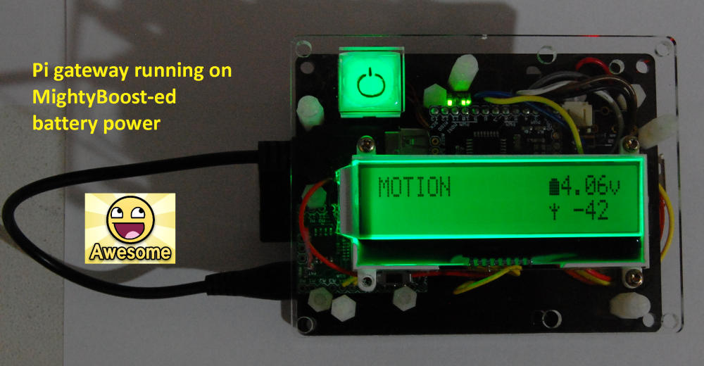
ATXRaspi is great for enhancing your Pi with a power button that will gracefully shut down your Pi without the need to login to do that. I’ve been running my Pi like that for at least a year. But I felt like I needed something new, more powerful.

Enter MightyBoost – a multi purpose PSU that can supply the power a Pi needs, and also be controllable by a Moteino (including wirelessly controllable if needed) such that it would duplicate the functionality of ATXRaspi. And most importantly to be able to run it on battery backup in case power is lost, to avoid SD card corruption and downtime. Also it can monitor the battery (via Moteino A7) and shutdown the Pi in time before the battery runs out, as a last resort. Without a Moteino it can be used as a general purpose 5V boost-from-lipo power supply, that can also charge your tablet/iPhone/droid/etc.

I have now upgraded my Pi gateway to using MightyBoost. I had to lasercut a new mid layer for my existing Pi Gateway lasercut case. I have posted the changes (corel and DXF files) in the github repo so you can customize &/or lasercut your own if you’d like. As usual, I like to cut the new template in cardboard and do a fitting test, measure any adjustments, re-cut if needed, then finally when it’s perfect cut it in the more expensive translucent acrylic. Continue reading →