
Programming
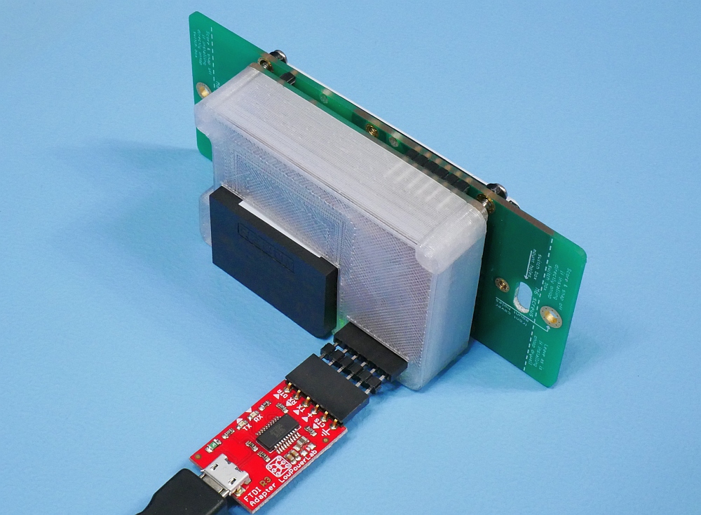
For programming and testing purposes, you can power and upload sketches via an FTDI-Adapter, just plug your FTDI-Adapter via the provided double header into the SwitchMote as seen below:
Upload the SwitchMote sketch into your SwitchMote Moteino the same way you’d program any Moteino. This sketch includes a configuration menu that helps setup the essential parameters of the Moteino in the SwitchMote such as frequency, node and network IDs, RFM69 type (W or HW), encryption key, optional description, etc. All these parameters are then stored to EEPROM for permanent storage. The sketch has no hardcoded radio settings, instead it reads the settings from EEPROM.
This keeps the sketch unchanged for all SwitchMotes and saves you from having to remember each Moteino’s radio configuration (ex. RFM69W vs RFM69HW). Additional settings could be added, like power level, bitrate, etc. Configure once and forget!

The ArduinoIDE serial monitor won’t work for using the config utility because of the way it emulates EOLs. So please use Putty instead, or an equivalent terminal app for the configuration utility.
The first time the sketch runs, it will check the EEPROM and detect there is no configuration set – it will then configure defaults (all 0 or empty settings, 915mhz for frequency). Use the menu to configure all parameters to match the hardware and your network settings:
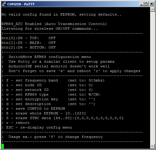
Here’s an example of using the menu to set the essential settings. After all settings are configured, don’t forget to (s)ave and (r)eboot the sketch via this menu to burn the settings into EEPROM.

After the initial configuration, your SwitchMote can be wired to mains and installed in the wall. The sketch will read the EEPROM configuration that was setup initially (shown above). The SwitchMote sketch also does several things:
- keeps track of which buttons were pressed, and manages the modes of operation
- any button can be in ON or OFF mode – reflected in GREEN or RED led status
- listens for BTNx:y tokens, to put button x in mode y, where x={0,1,2}, y={0,1}
- listens for SW:y tokens where y={0,1}, to turn the relay on or off and the associated button in that same state (reflected by the LEDs: green=ON, red=OFF)
- if the button associated with the relay (RELAY) is pressed then the Relay is turned ON or OFF depending on the mode that button transitions to
- if a button is held pressed for at least 3 seconds (configurable) it enters SYNC mode, explained below
- if a button has SYNC data it will notify the remote SwitchMotes to virtually “press a button”, and transition that button to the mode specified in the SYNC data
- if any button is held pressed for at least 6 seconds (configurable) it erases the internal SYNC data in EEPROM. This could be modified such that only the SYNC data associated with the pressed button is erased, not the entire SYNC data
- notifies the gateway, if any present, that a button was pressed
Note that SwitchMotes are designed to work independently and with each other without the need for a network gateway or coordinator (using the above sample sketch). A gateway is by default notified but the feature can be removed if not desired.
Also note that SwitchMote is highly flexible and can work without relay(s), in which case only the neutral wire N and a hot wire to either one of S1/S2 is needed (to power the electronics). In this case the SwitchMote can just act as a general purpose wall controller for other SwitchMotes or be customized to send other commands to other Moteinos. For instance you could open/close your garage (with GarageMote), or use the front panel LEDs to indicate the status of another node (ex: garage status, or mail delivered?). The sky is the limit of what you can do with a SwitchMote!