
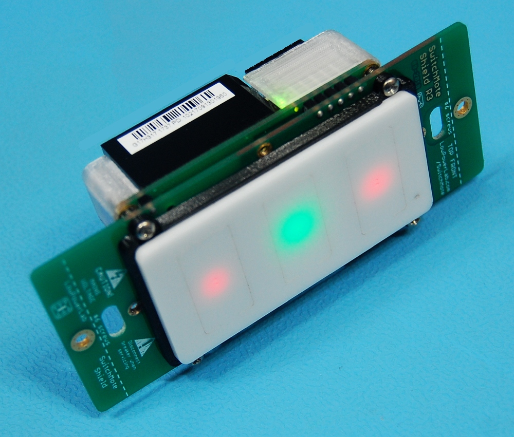
Reference Assembly (1x5A)
This page is kept for reference and shows the assembly steps for the original single 5A relay SwitchMote.
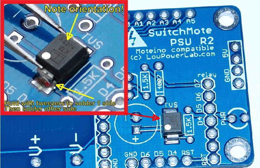
Step 1 – Solder TVS diode (the only SMD component)
Always solder from small to large components. Start with the SMD diode. The TVS zener diode ensures the output will never spike above 12V, in case there are any transients. This is to protect the low voltage side of SwitchMote. It is polarized so make sure you orient it correctly, see photos. The top has a line which should align with the line on the silkscreen (indicates cathode, may also be marked with silver marker dot). Use tweezers to hold it while you solder 1 side, then solder other side. If you are not SURE how to do this, it’s better to leave it unsoldered than to solder it incorrectly, the circuit will still work just fine without it.
Step 2 – Continue with PSU components soldering
Solder the 1.5K resistors, transistor, power LED, diode and capacitor. Mind the orientation on the diode, green LED, transistor and capacitor! Also solder the input diodes (polarized, note orientation!), and the fuse and varistor (non polarized).
 |  |
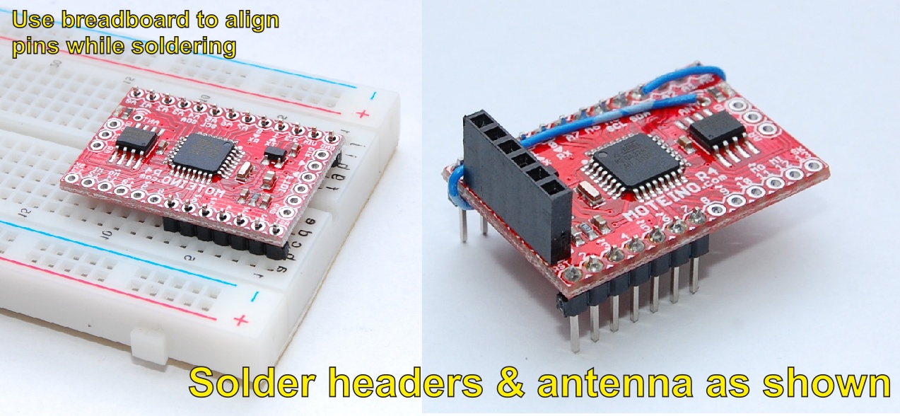
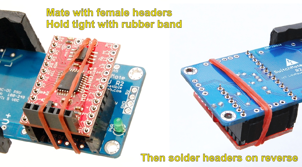
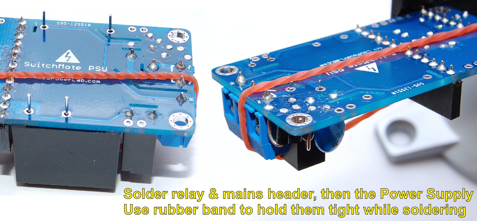
Step 3 – Solder Moteino headers, power supply, relay, terminal
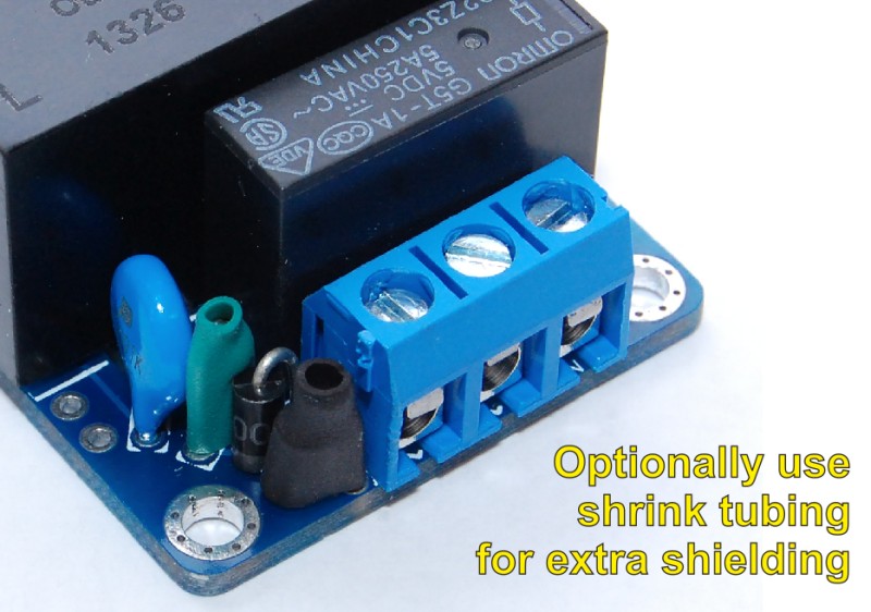
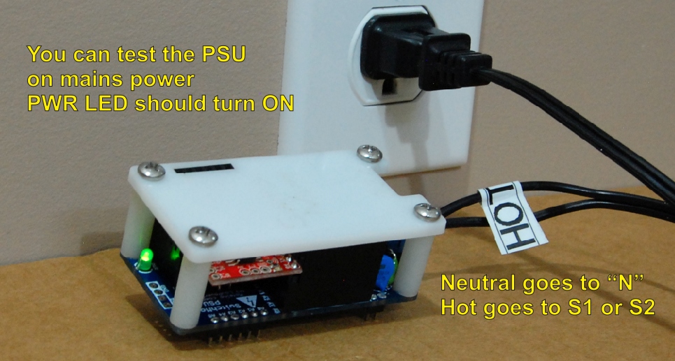
The Moteino headers are the next larger sized components so break apart the headers as illustrated, then solder to Moteino and then use Moteino as guide to hold in place the female headers to the PSU. Solder everything as shown. Then move on to the terminal, the PSU (largest component) and relay. Use a rubber band to hold everything flat to the PCB while soldering. You may then test the SwitchMote PSU by itself by powering from mains, but use a polarized power cord – one that goes in a power outlet only 1 way – test with continuity meter and mark Hot and Neutral wires. The neutral wire should be connected to the “N” terminal on the SwitchMote. The hot wire should be connected to either “S1” or “S2”. Also, you may solder the input mains wiring directly to the PCB (and skip soldering the terminal, stranded wiring recommended), then you connect those wires to the electric box using wire nuts. Upon plugging into mains outlet the “PWR” LED should come ON. You may use shrink tubing on the input diode and fuse if you want extra isolation on those components.
 |  |  |  |
 |  |  | |
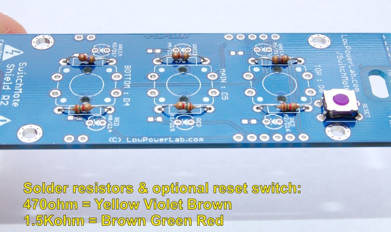
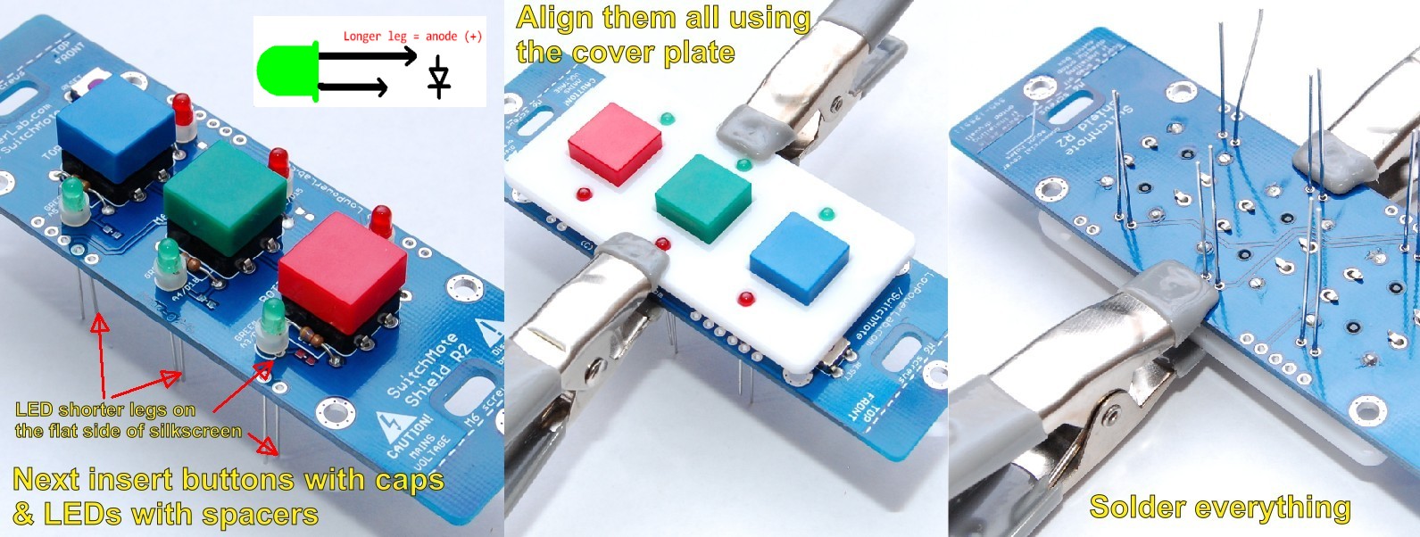
Step 4 – Solder the SwitchMote Shield
Insert the resistors, LEDs (with spacers), buttons (with caps installed) and optional RESET switch. The Switch is wired directly to the Moteino RST pin and can be used to reset the SwitchMote, but in general you should not have a need for it. At the moment of writing a hole is not made in the front cover to access the switch, you may do so by using a fine drill bit and make a small pin hole in the acrylic plate where the switch will reside. Note the switch is an SMD component, but bend the leads to adapt it to the PCB through holes. Then align the buttons and LEDs with the front cover, use small clamps to hold everything tight and then solder everything on the other side. Mind the LED polarity as illustrated, then trim all the leads as flat and neat as possible before proceeding:
 |  |  |
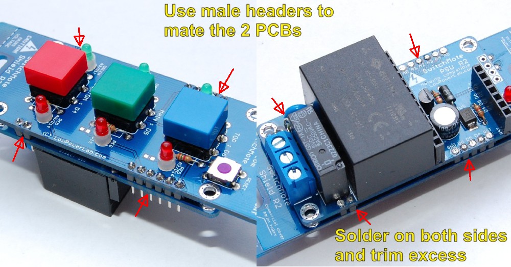
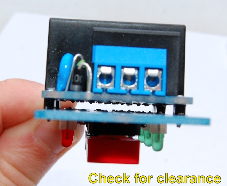
Step 5 – Mate the SwitchMote PSU with the Shield
There are 4 male headers you broke apart in a previous step. These will mate the two PCBs. The plastic tabs on the headers provide spacing between the Shield and the PSU. You should check for clearance and any improperly trimmed leads before you solder the two together. Once soldered, trim the excess headers on the longer side.
 |  |
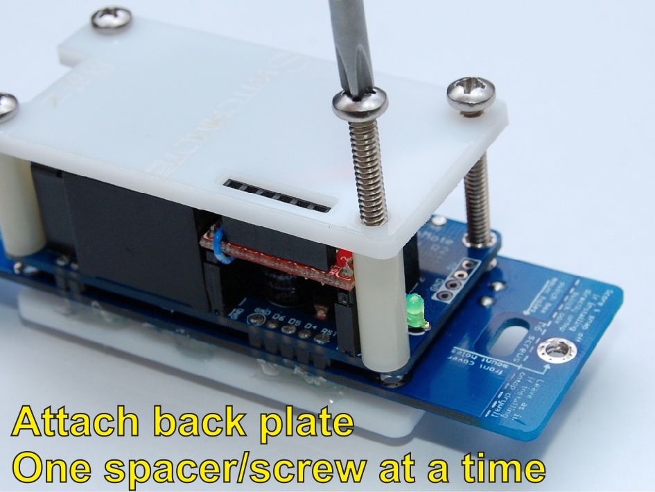
Step 6 – Attach acrylic covers
Reset switch – If you need to access the reset switch you may drill a fine hole in the front cover for it. The front cover can be attached with hot glue. Use the M6 screws and nylon spacers to attach back cover. The Moteino FTDI header should protrude through the back cover slot for easy access. You may wrap electrical tape around the screw spacers to add more isolation.
 |  |
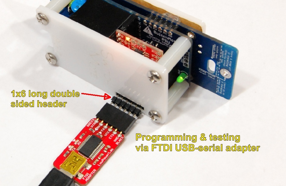
Step 7 – Programming test
Use the provided 1×6 double length male header to mate with an FTDI Adapter. Make sure the FTDI adapter is connected correctly to the Moteino (components side same on both PCBs). Upon connecting the FTDI adapter to your computer the “PWR” LED on the PSU should turn ON indicating power to the whole unit. The Moteino LED might also flash for a little while as the FTDI adapter is initialized. Load a blinky sketch and change the blink pin to D9, then load it to the Moteino. The Moteino should now blink the LED. This all means that the PSU and Moteino are in working order, congratulations on the soldering job!
Moteinos are tested for upload/wireless functionality before they are shipped. If however for some reason (faulty soldering or some short somewhere) the LEDs don’t light up as described something is wrong and you should not use that SwitchMote assembly.
Actual programming and sample code are are provided in the dedicated section below, also see this blog post.