

Assembly
MotionMote R4 was designed with ease of assembly in mind. There are only a few steps required and minimal soldering.
Add the acrylic round standoff to the PIR sensor. Do not force the PIR sensor pins into the standoff holes – if there is any debris in the 3 lasercut holes, remove them with a pin. Insert and solder the PIR sensor as shown:

Proceed to adding the LED, the helical antenna and the battery holder. The provided helical/spring antenna could be mounted flat as seen below, or the L side could be trimmed off and then soldered vertically.
Make sure everything is nice and flush with the PCB (trim the LED leads) as this is important when putting everything in the case – when finished your PCB should look like this:
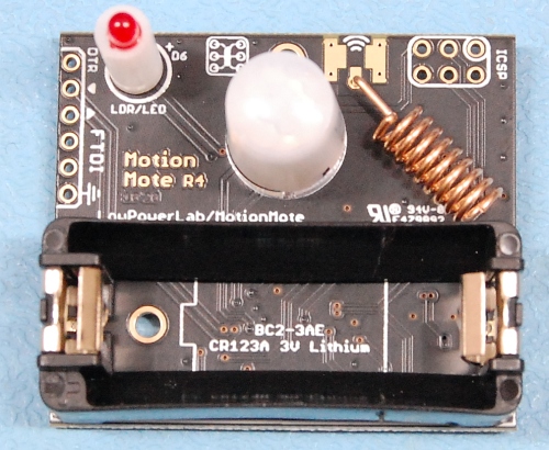
The spring helical antenna is a really great performer for most around the house needs – I tested this in various common and more difficult environments and it was always able to push messages through without problems. However if you had a specific antenna you wanted to try, you will notice a set of SMD pads at the antenna connection. You can use these pads to solder an SMA connector or a u.FL/IPEX connector to attach external antennas (the u.FL is a little tricky if you haven’t soldered SMD components but quite doable). In this case you would need to drill/modify the enclosure to take the antenna connection outside the box.


It is now time to complete the programming step before final assembly inside the enclosure.
You will notice there is no power switch on the MotionMote R4. As soon as the Battery is inserted it will start transmitting.
Carefully insert the PCB into the enclosure at an angle with the battery going in first. Wiggle it as needed to get past the mounting screw corners. Use one of the screws to attach the PCB to the mounting post inside the enclosure.

Finally, attach the front cover with the remaining 4x screws:
