Overview

This is a guide to assembling, programming and using the MotionMote. Please read the whole guide before attempting to assemble it, to avoid any errors – the assembly order matters! Familiarize yourself with the parts and their function.


Assembled with the ultra low power EKMB1101111 Panasonic PIR motion sensor:


Kit components

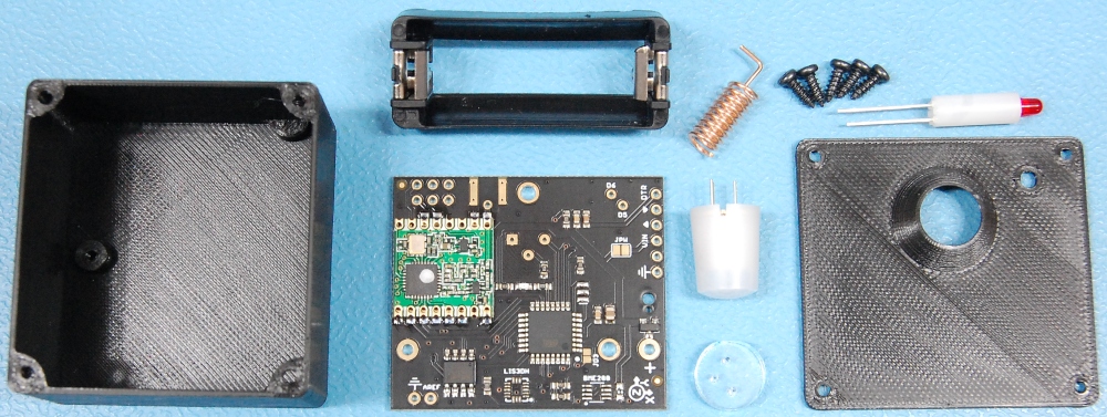
The kit contains most of the following components:

  • CR123A battery holder
  • PCB with soldered RFM69HCW radio (868-915mhz)
  • Right angled helical antenna
  • Ultra low power EKMB1101111 Panasonic PIR sensor
  • laser cut acrylic standoff for the PIR sensor
  • red LED with standoff
  • 3D printed enclosure with 5X mounting screws


Battery requirement

The battery is not included in the kit. You will need to source a CR123A Lithium battery. You might already have some for other devices. These batteries are very affordable and should last a long time in the MotionMote R4.

These batteries are non rechargeable. Once the battery runs out you will have to replace it.

Assembly

MotionMote R4 was designed with ease of assembly in mind. There are only a few steps required and minimal soldering.

Add the acrylic round standoff to the PIR sensor. Do not force the PIR sensor pins into the standoff holes – if there is any debris in the 3 lasercut holes, remove them with a pin.  Insert and solder the PIR sensor as shown:

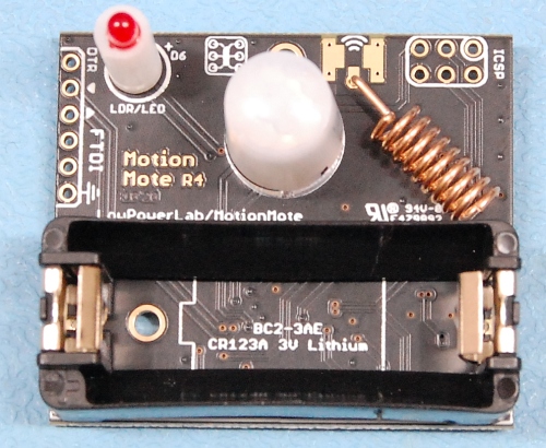
Proceed to adding the LED, the helical antenna and the battery holder. The provided helical/spring antenna could be mounted flat as seen below, or the L side could be trimmed off and then soldered vertically.

The LED is polarized – the longer leg goes to “+” on the PCB.

Make sure everything is nice and flush with the PCB (trim the LED leads) as this is important when putting everything in the case – when finished your PCB should look like this:

The spring helical antenna is a really great performer for most around the house needs – I tested this in various common and more difficult environments and it was always able to push messages through without problems. However if you had a specific antenna you wanted to try, you will notice a set of SMD pads at the antenna connection. You can use these pads to solder an SMA connector or a u.FL/IPEX connector to attach external antennas (the u.FL is a little tricky if you haven’t soldered SMD components but quite doable). In this case you would need to drill/modify the enclosure to take the antenna connection outside the box.

It is now time to complete the programming step before final assembly inside the enclosure.

You will notice there is no power switch on the MotionMote R4. As soon as the Battery is inserted it will start transmitting.

Carefully insert the PCB into the enclosure at an angle with the battery going in first. Wiggle it as needed to get past the mounting screw corners. Use one of the screws to attach the PCB to the mounting post inside the enclosure.

Finally, attach the front cover with the remaining 4x screws:

Programming & Powering

The sample MotionMote sketch is posted here. Don’t forget to change the radio settings before uploading. For the lowest possible consumption remove the D5/D6 LED handling code, or simply delete the content of the #define LED_HIGH and #define LED_LOW directives – mind that doing this also means there is no visual indication when motion/packets are transmitted.

You will program the MotionMote PCB through the 6 pin “FTDI” serial connector with the help of a USB-FTDI Adapter such as this one. The 1×6 header remains unpopulated and you simply use another male header to hold against this header when you do the sketch upload. Or you may choose to solder a straight 1×6 male header for more convenience, but ensure you solder it on the battery side so it can fit in the case.

Once you have the Moteino AVR boards package installed in Arduino IDE, select Moteino-8Mhz as the target board. The boards are loaded with the Dualoptiboot bootloader which accepts new firmware/sketch serial uploads at 57600baud, making them more/less equivalent to a Moteino-8Mhz.

Powering the MotionMote during programming

Please notice there is a JPW jumper on the board. To facilitate testing the boards may be shipped with this JPW jumper soldered, which powers the board from the FTDI (VIN) header).

You have two options to power the board during programming:

  • JPW Jumper OPEN (desolder it or cut it open): this disconnects the board VCC power from the FTDI header VIN. The can be powered by the battery only to ensure no more than 3.6v (the maximum voltage supported by the PIR sensor, radio module, flash memory, and optional MEMS/accelerometer and BME280 sensors). In this case you insert the battery and quickly upload the sketch, to avoid draining a constant 15mA from the battery. Once the upload is complete the consumption will fall to a mere few microamperes.
  • JPW Jumper CLOSED (soldered/bridged): this mode will provide power through the FTDI header VIN pin. In this case do not insert a battery during programming (the VIN pin would push power into the battery!). The important thing to remember is to only power the board from a 3.3V FTDI adapter (not a 5V FTDI adapter), since there is no LDO on the board and the PIR/radio/flash memory  and sensors can only take up to 3.6V!
Please note that the FTDI Adapter offered by LowPowerLab supplies 5V on the VIN pin, and can be modified with a jumper on the bottom to provide 3.3V instead.

For a one time programming effort, the FTDI header can be left unsoldered and manually pressed into the pin holes during programming. Below is an illustration of an FTDI Adapter attached with a temporary (unsoldered) 1×6 right angled header, ready to program the MotionMote R4:

The red LED_BUILTIN (D9) is on the bottom, along with the other SMD components. This will flash just like a Moteino LED during uploads, but thereafter will be unused. Once the sketch is successfully loaded, the MotionMote is already functional and you’re ready to fully assemble it inside the enclosure, revisit the assembly step for this detail.

Powering for normal use

After the MotionMote is programmed it’s time to insert the CR123A battery and deploy it in the desired location to sense motion and other other environmental parameters (through the optional LIS3DH/BME280 sensors).

Using with PiGateway

If you’re using the PiGateway GUI this will make it easy to integrate and trigger motion events.

Revisions & Schematic

Revision R4

This is the latest revision and comes fully integrated without the use of a separate Moteino. It uses a compact helical antenna mounted inside the enclosure, for great performance around the house. A single PCB with all accessories mounted on it makes for an overall compact design, but still in kit form, perfectly suitable for self assembly and unobtrusive placement anywhere motion needs to be detected or a SwitchMote turned ON by a motion event.

Revision R3

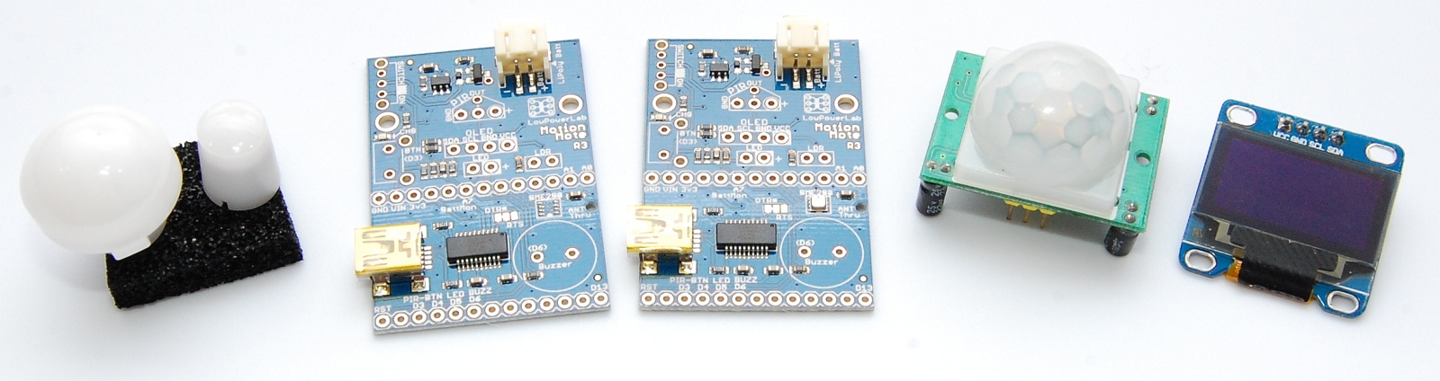
This revision had been tweaked for lower power overall. In addition it allows for Panasonic ultra low power PIR sensors to be installed instead of the default chinese HC-SR501 sensors. These Panasonic sensors are much smaller and available in idle consumption as low as 1uA, although they come at a steep price. It also features an optional BME280 temperature/humidity/atm-pressure sensor. The power switch has changed to a much more robust part. There are some solder jumper pad changes and new jumpers that allow more flexibility. The charging rate was changed to a default of 212mA (4.7K resistor). Pullups (4.7K) were added to SCL/SDA pins. An antenna through hole was added so it’s easy to route it straight to the back cover slot. A charge enable solder jumper was added – this is useful when powering from 3XAA/AAA batteries – cut it open to disable charging, resolder to re-enable it.
DSC_9817

Revision R2

Revision2 changed to PCB ENIG gold finish and fixes some bugs, most notably the FTDI chip addition of 27ohms inline on the D+/D- traces for better signal integrity. Below are some shots and details of these changes.