Assembly
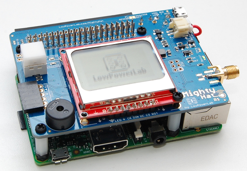
This is a guide to assemble, solder and install MightyHat ontop of your Raspberry Pi. Here is the complete MightyHat kit: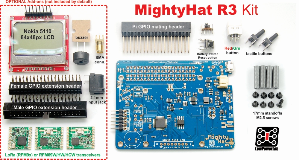
Start with small/short parts first and work your way to the taller/bulkier parts.
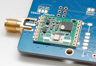
- Solder the transceiver and SMA connector (if any) if you haven’t had a transceiver already soldered. Make sure you orient it the right way, as shown in the photo.
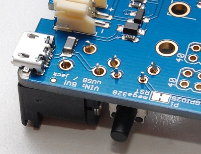
- Solder the RST tactile button and the 2.1 power jack (if any).
- Solder the battery slide switch. This is useful to cut off the battery without needing to unplug it, say if you wanted to ship a Pi with a MightyHat and battery plugged but not powered/active.

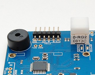
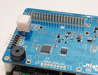
- Solder the buzzer if you have one (either orientation is fine).
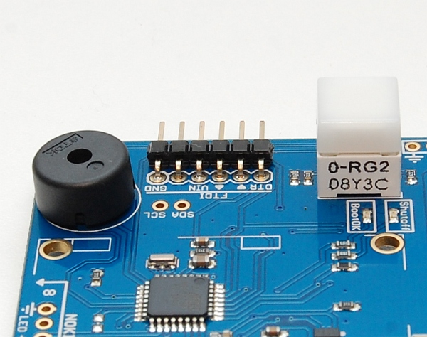
- Insert the Red/Green tactile button. The leads are easy to bend so be careful when you insert this one not to break them off. It also matters which way you insert it. Look at the picture and orient it with the black writing on the inside of the PCB.The R/G button is a tactile button that has two integrated LEDs:
- a red LED wired to D9
- a green LED wired to D6
The button itself is wired to A2. While this can be used as a general purpose button, the sample sketch shows how to use it as a power button, to turn ON the 5V* output rail and power the Pi.
- Solder your extra extension header (if you have one).


- Attach the hex standoffs to your Pi mounting holes. New kits are shipped with 3D printed 17mm standoffs and M2.5 metal screws to mount on the Pi. First attach the standoffs to the MightyHat PCB, do not over tighten the screws:

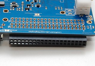
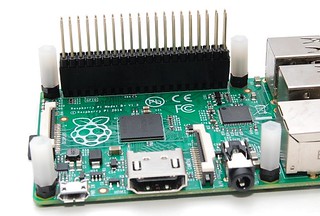
- Insert the mating header into the Pi’s GPIO header. Then insert the MightyHat on top of that header and solder the mating header onto MightyHat.
- A 1000uF capacitor was included in the kit and while in most cases it might not be needed, it’s a good idea to solder it anyway. This capacitor helps with voltage dips (on the MightyHat 5V* output) if there are large loads or load spikes on your Pi, and helps prevent brown-outs. It can be mounted top or bottom, wherever you can find room for it (yielding room for the battery and LCD, if any). Just make sure you get the polarity right:

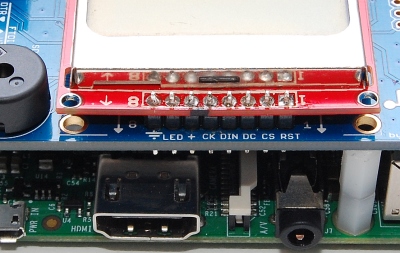
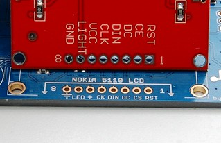
- Solder the LCD using the included 1×8 header. If you source your own Nokia 5110 LCD ensure the pinout order is the same as the one marked on the MightyHat mating header. The LCDs usually have 2 parallel headers, make sure to match the pin order, they are numbered, match 1 with 1, 8 with 8, only one header will match the silkscreen numbering so be careful not to solder the wrong side of the LCD:
 NOTE about Nokia 5110 LCD: these LCDs are pressure fitted to the PCB contacts through a rubberized connector. If the metal shroud is not tight, the actual LCD might be loose and contrast or image could be compromised. You should double check this metallic shroud is secured at the back of the PCB through the 4 metal tabs. Also it’s a good idea to first solder the header to the LCD and test it out on your Arduino/Moteino with the given sketch or an example sketch in the u8glib library, to ensure proper contrast is achieved and the LCD is working. It’s easier to debug this potential issue before it is soldered to MightyHat. An alternative is to solder a ribbon cable which allows the LCD to be flipped over or more easily removed if later required.
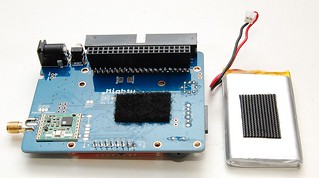
 - If you want the backup function to prevent a potential SD card corruption or system downtime during a power outage, you can attach a Lithium Polymer battery at any time. When external power (5V) is present, the battery is charged. If external power is lost, the battery picks up and keeps your Pi running until power comes back or until the battery runs out at which point MightyHat shuts down your Pi safely as a last resort. I recommend at least an 2Ah battery, this one from Adafruit works well. You can use velcro or double sticky tape to attach it to the bottom of MightyHat.
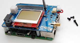
- To secure MightyHat ontop of your Pi, add the remaining 4 screws into the standoffs. Note that one is mounting hole is shared with the LCD, mount this screw first, do not over tighten this to avoid the LCD PCB to warp. For the other 3 standoffs you may need to shorten the screws to make them fit into the standoff, cut them with a razor or utility knife.
- Assembly done, you can now move onto the programming part!