

Bootloader and basic testing
20Once the board is finished, the most important check is the LDO regulator output voltage, it should read 3.3V on the “3v3” pins (on the top left and also on the 1×3 header on the right of the board).

So far so good!
The next step is to “burn” the 328p MCU with the bootloader. This is an essential small special permanent program that sits at “the end” of the MCU internal flash memory, and makes it very easy to load other user programs (your sketches) through the serial port. Another important part of this special initial programming is loading the MCU “fuses”. These are special registers that determine basic functions like the core frequency, clock source, watchdog, startup delays, memory locking etc.
All genuine AVR based Moteinos come with Dualoptiboot, a modified version of the Optiboot bootloader used on ArduinoUNOs. This bootloader is special because it allows wireless programming (aka OTA), when used with the external FLASH-MEM, see more details about it here.
To burn the fuses and bootloader you will need an ISP programmer. There are many such ISP programming clones, and even an Arduino UNO can be used to ISP-program another AVR chip, but a dedicated programmer is recommended. An older official programmer made by Atmel is the AVR-ISP MKii which is now discontinued but may be found on ebay or other sites. You can also use Microchip’s Pickit2. On the PC side, you can use avrdudess, or even AtmelStudio – but which is a lot bulkier and requires a long install.
You should power the Moteino via the GND and VIN pins. If you use the MCP1703 LDO, you can use up to 16V as input voltage to the Moteino. Other variants include the MCP 1702, 1701, 1700 which all output 3.3V but their upper input voltage limits are lower.
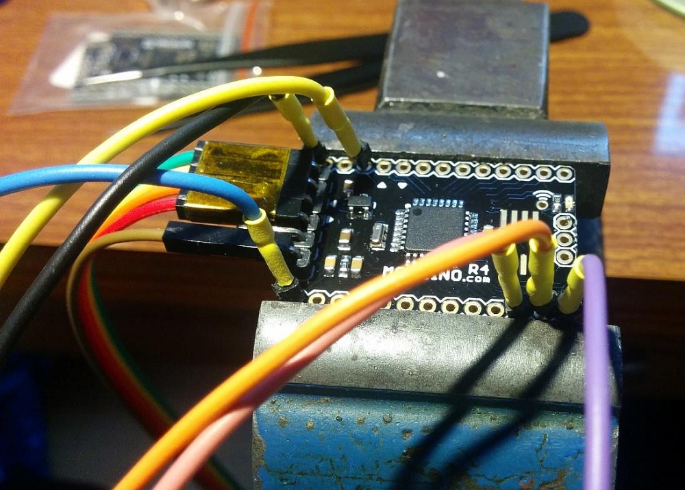
For ISP programming you will need to connect the programmer to the Moteino’s ISP pins: MOSI, MISO, SCK, RST, GND, and VCC for sensing only). This is illustrated in the photo below.
You can use this precompiled Dualoptiboot HEX file. Here is an example of setting fuses and the bootloader: