Overview

In this short guide we will assemble a Moteino R4. This guide is a complement to the main Moteino guide and you should probably see that guide for reference. You may follow these steps to build another type of Moteino as well.

You can find the design files and BOM on Github, and you can order your PCBs at OSHPark (faster) or PCBs.io (cheaper, 4x boards instead of 3x). Here is the schematic for the components:

Here is the Moteino pinout diagram:

And an official Moteino R4 for comparison:

For SMD soldering, you can get fancy and use solder paste along with a stencil. It’s pretty cheap to order yourself a stencil from the cream-layer of your board, but if you’re brave and like tinkering with chemicals, you can see this method of making a DIY stencil from a soda can:

Here’s how it would reflow in an oven once the paste is applies and components are in place (thanks Lukapple for sharing the video):

But in this guide we keep things simple and just use hand placement and direct soldering.

Let’s get started!

Soldering - SMD!

Mount PCB in a vise, so that it won’t move while you work on it. The board was designed mostly for 0603 component size, but you can fit 0805 components without much trouble.

Before you begin, here’s a quick SMD soldering tutorial you might find useful:

Place solder on one pad of the atmega328p footprint. Align the 328 chip to pads and solder that pin and pad. Check the overall alignment of the chip to the pads and adjust now if needed. Then solder one more pin on the opposite sides, this will lock the IC in place while you solder the other pins.

Pay close attention to the orientation of the atmega328P chip!
The dot on the chip has to match the dot on the board (upper left corner of the PCB pad).

To make soldering easier and solder reflow better add flux on all pads/pins. This will also help prevent solder bridging. The easiest way to apply flux is with a bottle with a syringe needle attached, or even more convenient – with a flux pen.

Solder all the MCU pins. Less soldering results in less problems, less in this case is better. Double check your work, make sure you don’t have any solder bridges! Do you see any? With SMD work, a stereo microscope is a great tool to have both to see what you’re doing, and to inspect small components. Can you spot a bridge in the photo below?

Another indispensable tool for SMD work and rework is a hot air station, they are quite affordable these days. If you do lots of SMD work, make your life easier and add one to your tool inventory!

Use hot air to solder the 1uF and 100nF caps, 10k resistor are next. Here the capacitors size is 0805. If you don’t have a hot air station, use tweezers to align-hold the part in place, and tin the side where you had solder on the PCB pad. Then add flux if needed, and solder the other side. Move on to the LED and its resistor.

After all components are soldered, use isopropyl alcohol and Q-tips to dissolve and clean flux and other soldering residues. Hopefully everything looks nice and shiny!

Bootloader and basic testing

20Once the board is finished, the most important check is the LDO regulator output voltage, it should read 3.3V on the “3v3” pins (on the top left and also on the 1×3 header on the right of the board).

So far so good!

The next step is to “burn” the 328p MCU with the bootloader. This is an essential small special permanent program that sits at “the end” of the MCU internal flash memory, and makes it very easy to load other user programs (your sketches) through the serial port. Another important part of this special initial programming is loading the MCU “fuses”. These are special registers that determine basic functions like the core frequency, clock source, watchdog, startup delays, memory locking etc.

All genuine AVR based Moteinos come with Dualoptiboot, a modified version of the Optiboot bootloader used on ArduinoUNOs. This bootloader is special because it allows wireless programming (aka OTA), when used with the external FLASH-MEM, see more details about it here.

To burn the fuses and bootloader you will need an ISP programmer. There are many such ISP programming clones, and even an Arduino UNO can be used to ISP-program another AVR chip, but a dedicated programmer is recommended. An older official programmer made by Atmel is the AVR-ISP MKii which is now discontinued but may be found on ebay or other sites. You can also use Microchip’s Pickit2. On the PC side, you can use avrdudess, or even AtmelStudio – but which is a lot bulkier and requires a long install.

The Moteino is NOT powered by the programmer and requires separate power during ISP programming!

You should power the Moteino via the GND and VIN pins. If you use the MCP1703 LDO, you can use up to 16V as input voltage to the Moteino. Other variants include the MCP 1702, 1701, 1700 which all output 3.3V but their upper input voltage limits are lower.

For ISP programming you will need to connect the programmer to the Moteino’s ISP pins: MOSI, MISO, SCK, RST, GND, and VCC for sensing only). This is illustrated in the photo below.

In the photo below, the 3v3 pin is used to power the Moteino. Voltage on this pin should not exceed 3.3V, especially if the transceiver/RFM69 radio module and/or the FLASH-MEM chip are already installed – those parts are not 5V tolerant. 

You can use this precompiled Dualoptiboot HEX file. Here is an example of setting fuses and the bootloader:


Radio and testing

Once the bootloader is burned on the 328p MCU, the board is ready to accept user sketches straight from the Arduino IDE or even through the command line via avrdudess/avrdude.

Here we illustrate how to solder an RFM69HW module.

Notice the orientation of the module before soldering, this is very important, soldering it wrong will render the module non-functional!

You may also add the W25X40CLSNIG 4MBIT FLASH-MEM chip (datasheet), this is useful if you plan to try wireless (OTA) programming, or want to use it as extra memory (like a small hard drive for your Moteino!).

To test the radio module, you will need another Moteino or a different board with an RFM69 radio – at least two are needed to make a communication link. Once ready, you can look at the many examples in the RFM69 library. For basic testing or a radio link you can use the Node and Gateway examples, or the TxRxBlinky example which can be used on both the sender and receiver units, along with a button for user interaction.

GPIO testing

You may also want to test the other GPIOs of your DIY Moteino. Here are some simple analog pin tests. We can use a potentiometer as input to A6 and A7, and the onboard LED (on digital pin 9) to be PWM-ed as output depending on the pot position. Here is the test sketch for testing A6 input:

const int analogInPin = A6;  // Analog input pin that the potentiometer is attached to
const int analogOutPin = 9; // Analog output pin that the LED is attached to

int sensorValue = 0;        // value read from the pot
int outputValue = 0;        // value output to the PWM (analog out)

void setup() {
  // initialize serial communications at 9600 bps:
  Serial.begin(9600);
  pinMode(0, OUTPUT);
  pinMode(A4, OUTPUT);
  digitalWrite(0, HIGH);
  digitalWrite(A4, LOW);
}

void loop() {
  // read the analog in value:
  sensorValue = analogRead(analogInPin);
  // map it to the range of the analog out:
  outputValue = map(sensorValue, 0, 1023, 0, 255);
  // change the analog out value:
  analogWrite(analogOutPin, outputValue);

  // print the results to the Serial Monitor:
  Serial.print("sensor = ");
  Serial.print(sensorValue);
  Serial.print("\t output = ");
  Serial.println(outputValue);

  // wait 2 milliseconds before the next loop for the analog-to-digital
  // converter to settle after the last reading:
  delay(2);
}

And here’s a test sketch for testing A7 input:

const int analogInPin = A7;  // Analog input pin that the potentiometer is attached to
const int analogOutPin = 9; // Analog output pin that the LED is attached to

int sensorValue = 0;        // value read from the pot
int outputValue = 0;        // value output to the PWM (analog out)

void setup() {
  // initialize serial communications at 9600 bps:
  Serial.begin(9600);
  pinMode(1, OUTPUT);
  pinMode(A5, OUTPUT);
  digitalWrite(1, HIGH);
  digitalWrite(A5, LOW);
}

void loop() {
  // read the analog in value:
  sensorValue = analogRead(analogInPin);
  // map it to the range of the analog out:
  outputValue = map(sensorValue, 0, 1023, 0, 255);
  // change the analog out value:
  analogWrite(analogOutPin, outputValue);

  // print the results to the Serial Monitor:
  Serial.print("sensor = ");
  Serial.print(sensorValue);
  Serial.print("\t output = ");
  Serial.println(outputValue);

  // wait 2 milliseconds before the next loop for the analog-to-digital
  // converter to settle after the last reading:
  delay(2);
}

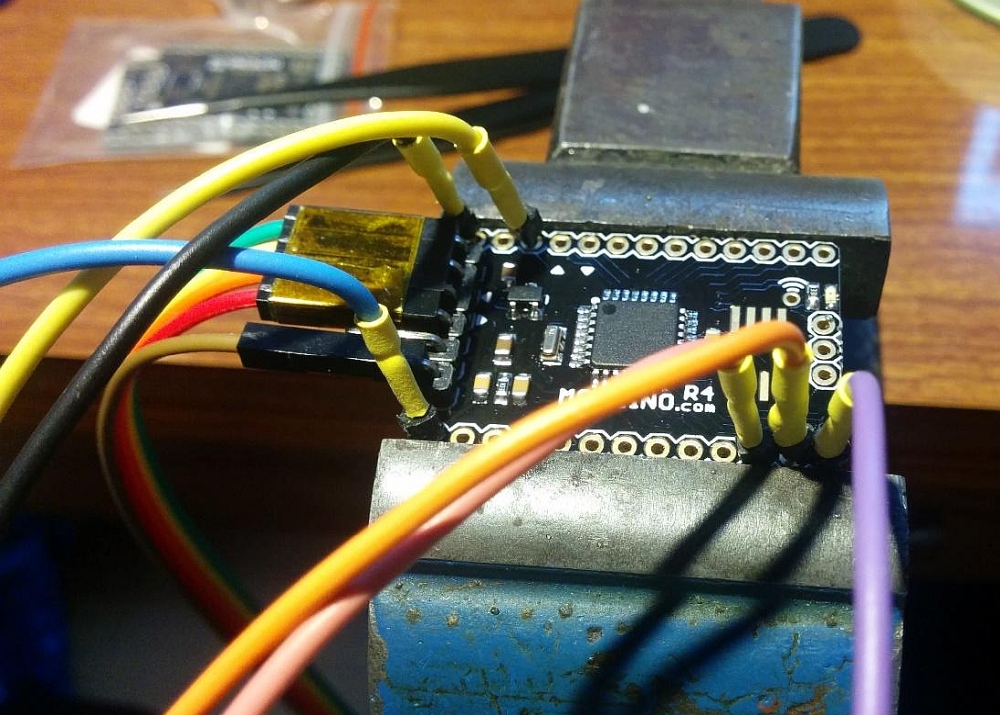
For both sketches you will need a potentiometer (any will work) as seen in pictures above. Here’s the LED output at low duty cycle:

Here is the same sketch with the pot turned all the way, the LED is now very bright:

And finally here’s a sketch for checking all other GPIO. This sketch outputs a ~100Hz square wave signal on every output except A6,A7:

void setup() {
  for(byte i=0;i<19;i++) {
    pinMode(i, OUTPUT);
  }
}

void loop() {
  for(byte i=0;i<19;i++) {
    digitalWrite(i, !digitalRead(i));
  }
  delay(5);              
}

Congratulations, you have assembled and tested your own DIY Moteino, you are on the way to becoming an SMD soldering master!