Importing a laser cutter from China

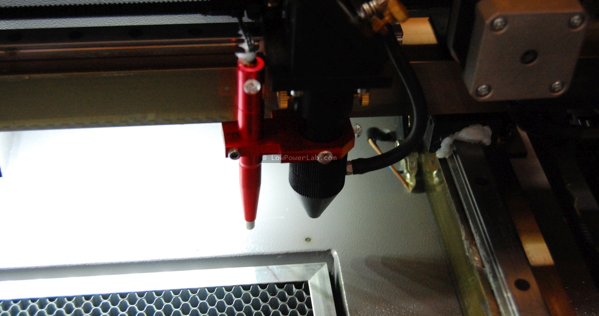
As a break from the pick and place posts, in this article I’d like to aggregate my research about laser cutters and my experience importing a chinese laser cutter. There’s a wealth of knowledge scattered around the web, and this article won’t meet everyone’s search criteria, but hopefully this will be a resourceful stop for those that are in the search for a similar machine on a budget that can achieve the same results as a high end laser cutter/engraver.

I’ve been laser cutting my stuff at Techshop Detroit for a while since as an instructor I had free access to their shop and CO2 Epilog Helix lasers. That was cool but I didn’t have class very often and often when I had an immediate need to cut/engrave on the laser I would have to burn the gas and time to get there, about a 30 mile/35 minute drive (no traffic). Also I had to make sure to schedule well in advance to reserve a spot. And to top it off, they had a major ventilation issue for several months so cutting acrylic was restricted to 1 hour, not nearly enough to do what I needed. A single 24×18″ panel full of SwitchMote covers would take 45 minutes just to cut. Not counting setup, adjusting the machine, making sure it’s clean and ready to go, testing a few cuts on scrap, etc. In short, this was not scaling very well.

So I decided to look for a  better alternative, knowing my laser engraving needs would only grow. The common denominator answer was to get my own CO2 laser cutter! Yikes, both exciting and scary thought. Exciting because it would solve all the issues I mentioned and save me tons of time, scary because it’s a big thing to haul around, noisy, hazardous, dangerous if mishandled, requires ventilation, maintenance, liability, etc. Doh…

Anyway, so what were the options? Continue reading →
Pick and place – entry level options

Startups that manufacture electronics are faced with a limited set of choices when it comes to getting their hardware assembled. Each of the methods below have an array of possible approaches, some good some less so. I will try to cover what I’ve seen in my quest, hoping this will be a good overview of what’s out there. If I miss details or interesting methods please let me know and I will keep this list updated. This is part one, where I look at options of assembly without getting into a real commercial pick and place.

Doing it manually. Everybody started here, including Adafruit, Sparkfun and others. It’s great and fun at first and you learn a lot about surface mount technology (SMT) and also gain respect for how hard quality assembly really is. And we’ve seen countless ways people do this around the world. Some spread paste with a toothpick or dispense with a DIY syringe, then place parts with tweezers. This works for about 5 minutes before you go crazy, especially if you go smaller than 0603. Others laser cut mylar stencils to speed up the paste deposition. I etch my own stencils from soda can aluminum, this is fast and works great. For placement I’ve seen people make some fancy ball bearing jigs to help them move their hand, a bit better.

This is very cool and I almost did this myself but I think it’s overkill and a bit slow and … more expensive than it needs to be for what it does, but I can appreciate the effort of its creator. One advantage of this fixture is the ability to better hover over larger PCBs while placing. FWIW the maker even went as far as mounting a camera to help placing the parts, a nice touch, but looking at his video of it in progress the angle of the camera looks weird and looking away on a monitor when you work with your hands is what cuts the speed. Here’s another one of the same kind for reference. I do the same as these, only probably faster, with my aquarium pump pick and place (hold your laugh for a moment there) which cost me about $20 in parts, took about 30 minutes to make, and has full stereo vision – my eyes, can’t beat that for the price. I like to brag about this method not because I’m using it, but because it’s probably the best 100% manual method I’ve seen. Why you ask? I can do up to 7-800 CPH (measured!) with it on less complex boards. The only downside is obviously having to sit there all the time, with some neck and back strain, and the part alignment is less than ideal, but paste reflow really helps. I’ve assembled many thousands of PCBs this way, it works nicely and gets stuff done, but it’s not great. I wish I spent all that time developing new projects. So what is better than this?

Continue reading →

PPM visit and Quad IVc/4000c pick and place demo

In an effort to deliver truly meaningful and comprehensive content, I will write a few articles about pick and place machines and SMT assembly, after many months of trial and error with various methods, in hope to help others who may want/need to get into SMT equipment and assembly. The focus will be on pick and place machines, my observations, what I learned in my prolonged research into pick and place machines over the last year, what some people say, what some companies end up choosing and why, what to look for, what to run away from, etc.

I first saw the article about the Quad IVc pick and place on Ohararp.com and was curious to see this machine up close.

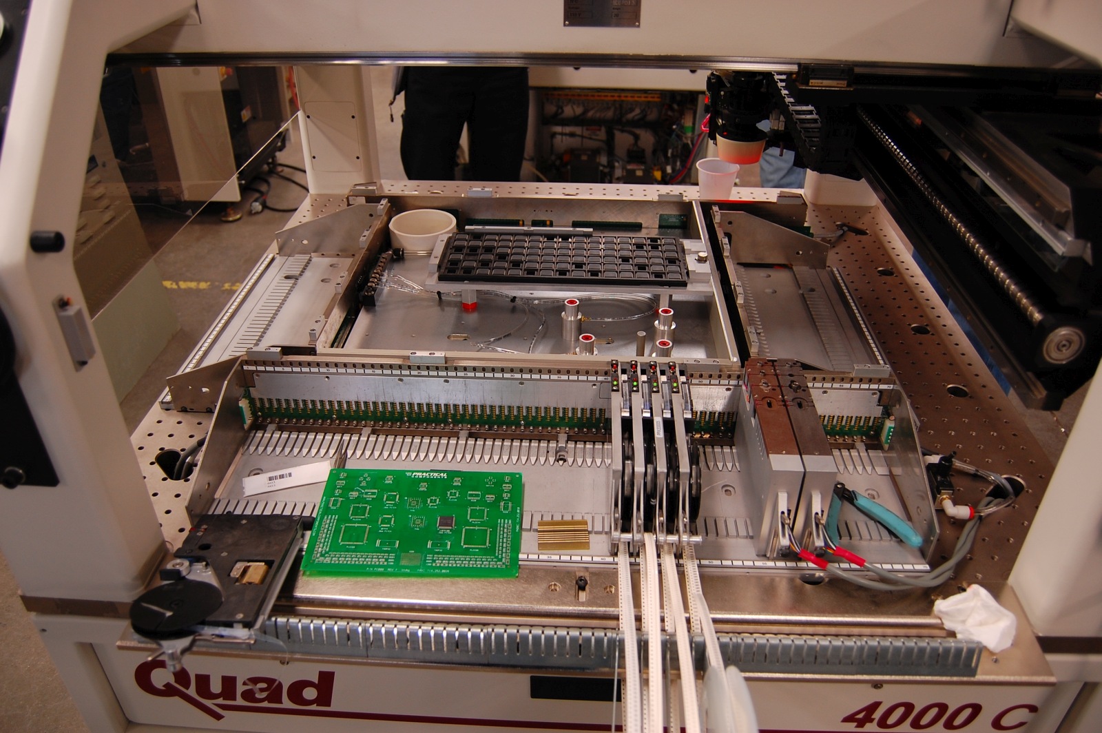
We visited PPM (Precision Placement Machines) some time ago and was able capture a few of the cool things we’ve seen there. This video shows a demo run and feeder setup on a Quad 4000c (Quad IVc upgraded to Windows 7).

I really took a long look at this machine and that’s why I took a day off to go out there (they are truly out in the country). Unfortunately there aren’t many resources on the web about these machines, at least not high quality pictures or videos, so I hope this will change that at least a little bit. The visit was very much worth it and the great staff showed us around and throughout the PPM facility. There’s too much to say about the visit and I hope to make some time to post more pictures later so here are a few more photos of the tour. Later I will expand on our observations on the Quad pick and place.

For now I will just post this video showing the Quad 4000c in action. It illustrates how the machine dispenses paste, places a range of components and finally how a feeder is setup:

Moteino controlled CNC mills Stencil8 tooling block!

If you’re wondering why the blog is so inactive lately it’s because there’s lots going on at Low Power Lab, and so not much time for blogging unfortunately.

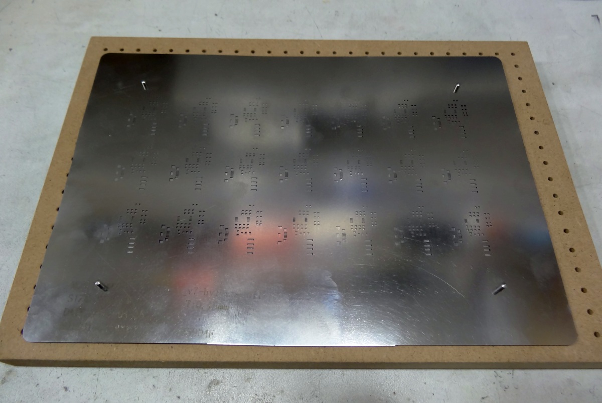
But among other cool things, I wanted to show a side project that I’ve had implemented with the help of a friend who has a CNC. I wanted to try a tooling block for the Stencil8 system for PCB-stencil alignment and paste application. Having this type of tooling block makes it easy when you get a new stencil.

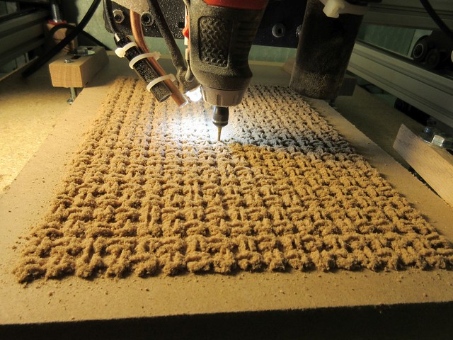
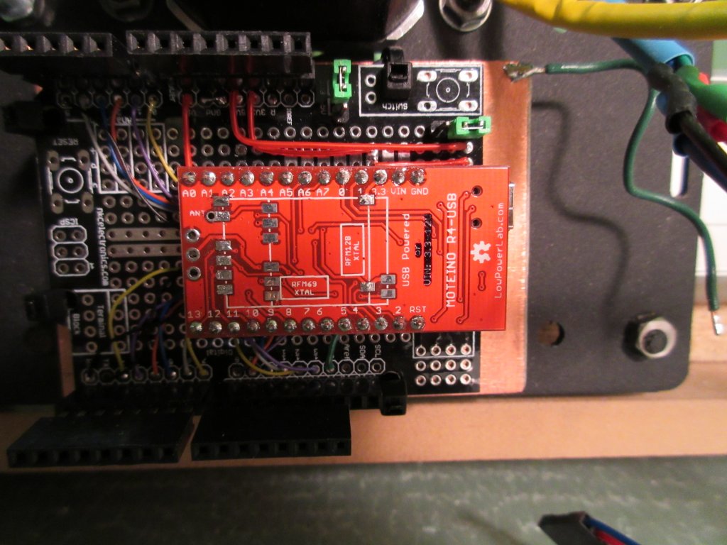
Instead of just getting myself a tooling block made I got a whole lot more. I never thought a Moteino could run GRBL and actually control the CNC, but it turns out it can!
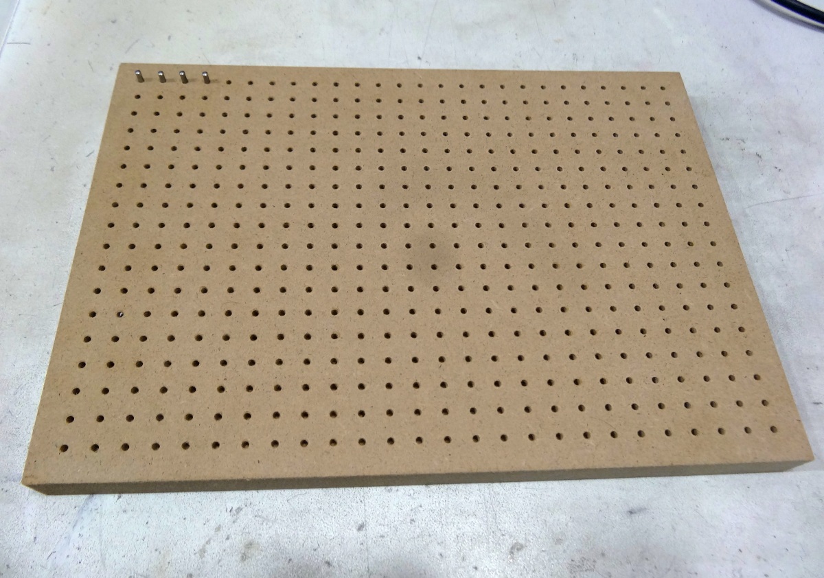
So the first attempt is a Stencil8 tooling block (really .. just a NxNcm grid of 2.5mm holes with top chamfers), made of MDF. You can get yourself an ALuminum one from here, but I thought I’d try MDF since it should work fine in most conditions. Yeah, I know AL is much more dimensionally stable with temperature/humidity changes, but it’s dry and cool in my shop. Milling AL takes much longer and is messier.
The exciting news is that Moteino is powerful enough to run GRBL and control a CNC:

Check out the video below for some CNC action, milling Low Power Lab in MDF:

Getting more serious about SMD production

I’ve been doing all manual SMD assembly ever since I started Low Power Lab, and still do at this moment. I find it too hard to outsource assembly and too prone to some issues.

Anyway, in the beginning there were tweezers, a microscope, and a toaster over for reflowing. I very quickly realized that the tweezer method was insane to put it mildly, the only worst thing that I can think of is actually soldering everything with a soldering iron instead of using paste. Nonetheless the first ever Moteino batch was tweezer-microscope+reflow assembled. Then I figured out how to make metal stencils out of soda cans. That works beautifully, costs next to nothing, and the more you make the faster and better it gets, and those stencils never wear out, unlike mylar or other plastic stencils. It’s the closest you will get to real stainless steel stencils. But I could only spread paste on 1 piece and it gets tedious, watch this video of how I actually do it. Panelizing PCBs sounded a bit scary.

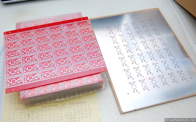
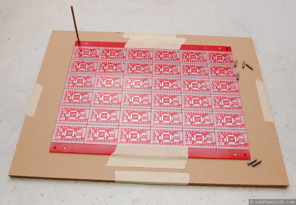
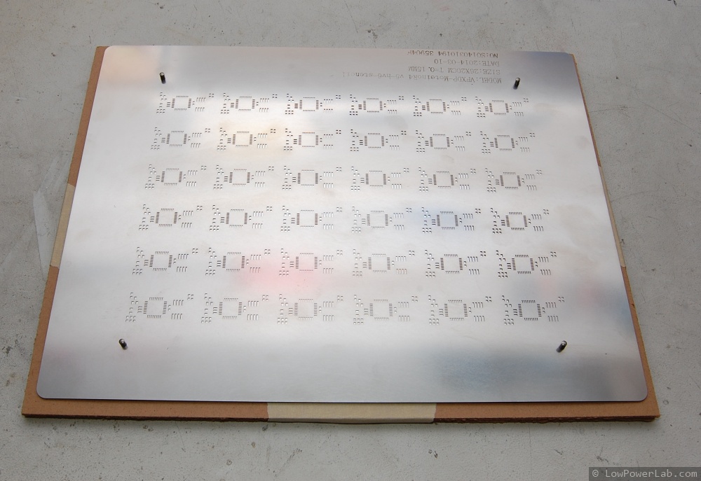
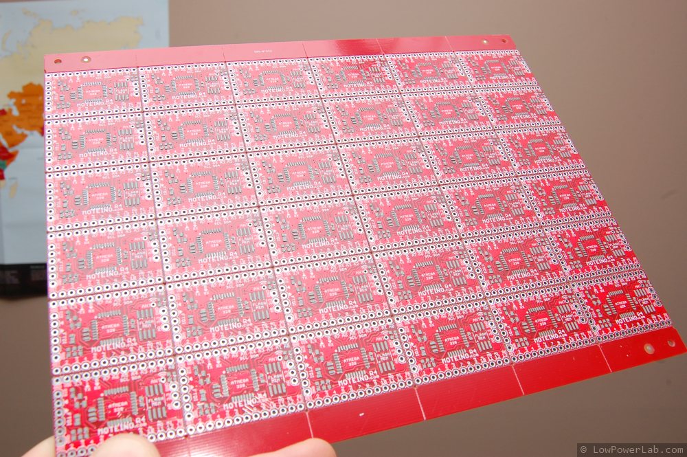
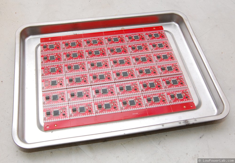
So finally I made the jump and panelized a batch of Moteinos recently. The panel has 2.5mm tooling holes that are spaced on a NxN cm grid (which would fit the Stencil8 tooling block), but quite frankly they could be spaced any way. The tooling holes match holes in the stencil such that the stencil alings perfectly with the PCB. The panels and stencils are made at Hackvana. I don’t have a tooling block because quite frankly I don’t think it’s needed (UPDATE: I actually had a MDF block milled – see this post for details). I drilled holes in some MDF using a 2.5mm drill bit (the thin sheets that come with the stencil are right size and perfect for the job), using the PCB to pilot the holes. Then 2.5mm steel tooling pins align the stencil with the PCB.

The time savings is significant, especially if multiple panels are assembled at once. I was reluctant at first and I was worried about the spacing between the PCBs and other things like that. But glad I did it and this is a first step towards more serious in house assembly. The v-scoring means the PCBs are snapped apart after reflowing, and the edges will be a bit rougher than the nicely routed PCBs I was used to. I do however snap the panels in 3 rows for easier SMD assembly with my pick and place vacuum tool. After reflow they are snapped into individual pieces. The panelization is done at the PCB fab for an extra fee.
The McMasterCarr parts for the pins and the drill bit are: here for the pins and here for the drill bit.

Next up: pick and place machine maybe? Haha.

So you can’t afford a $200 lightbox?

I’m going to try to break the blog silence with something worthwhile your precious reading time, my dear reader. There’s much to blog about and what’s going on at LowPowerLab but for now something simple.

I like to take nice pictures, it’s like giving candy to the eye. Because the images convey presentation. And good presentation is a paradigm of quality. Look at a good blog with crappy pictures – you will read but won’t be terribly impressed, right? Look at a less an average blog with great pictures and you will instantly follow it.

Until recently I took all the blog pictures on my white work desk but lately that’s gotten dirty from all the stuff I do on it but I’m too lazy to get everything off and add a coat of white paint, that’s for another day when I’m awfully bored. So I started using blank sheets of paper under the subject, that worked pretty nicely, but every shot took a few minutes to setup and get the right light and angle on the tripod so the light wouldn’t bounce too much off the ceiling etc, what a paaaain 8-( … OK – so looking around the web yields the typical results you will find on any product – cheapo lightboxes made of fabric, for around $30-$50, the nicer ones are $100-$200 or even more. I like to spend the extra buck on the nicer thing, but finding it impossible to spend that much on something as simple as a light box I thought – doh … how hard can it be to make one? Continue reading →

Laminator dimmer hack for PCB or stencil toner transfer

This post will walk you through a dimmer enhanced laminator mod that allows an alternative method to transfer toner to PCBs or metal stencils.

The clothing iron transfer method works pretty well to make metal stencils. But for larger stencils it might not be so feasible, and a lot of people reported that they could not get a consistent transfer with their irons, maybe because not all behave the same. I have to say there can be lots of potential points of failure in this process. It’s a lot of trial and error, and my stencil tutorial was meant to help with eliminating some of those failures that I’ve gone through. I decided to try the laminator mod to see how that works compared to the iron. Continue reading →

Reflow oven insulation

My reflow oven is very low tech. I haven’t modified it at all and even so I’ve been using it to reflow thousands of PCBs ever since LowPowerLab started.

It has top and bottom elements, but the heat does not distribute evenly, understandably so – you can see through it. Sometimes PCBs that were on the inside edge would take longer to reflow. Air escapes in several different places all over the oven enclosure, especially on the bottom front and back:

It’s time for a small improvement, adding some basic insulation in an attempt to stop air flow, keep the heat in and hopefully make it more evenly distributed. Continue reading →

Illustrated guide to making simple jigs for programming and testing

When I built the first revision of Moteino I had to come up with a way to program and test them quickly without having to solder the headers. I saw how others built complicated jigs for this purpose with all kinds of features, so I wasn’t very excited to do something like that.

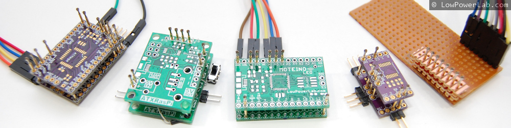
It needed to be quick and simple (without the ‘dirty’) and also without a lot of waste – spring loaded test probes (aka pogo pins) are expensive and when revisions change sometimes the positions/function of the holes change as well and I didn’t want to spend a lot of time/$ making a jig. So I just stacked two of the same PCBs as the target and used pogo pins to hold the PCBs together (or rather the PCBs to hold the pins aligned and leveled). That worked great, with one hand I could hold/press the target PCB on top of the pogo pins, with the other do the programming.

So what are ‘pogo pins’?
They are small cylinders with a piston tensioned by a spring that pushes it out and they come in all sorts of lengths, thicknesses and tip configurations (they actually have codes for each tip type and length), a picture is better than words:

spring_loaded_test_probe_pogo_pin

Other PCBs required testing so I built quite a few such testing jigs, here are a few examples, notice the simplicity:

programming_jig_spring_loaded_test_probe_pogo_pin

The rest of this blog entry is a guide to making jigs like these. Your final solution and it’s capabilities is only limited by your imagination. For instance you might test if a pin goes high by soldering an LED, or turn a pin HIGH/LOW by soldering a switch.

Continue reading →

DIY manual SMD pick and place machine for $20

I’ve shot this video over several days a few weeks ago and finally had some time to put it together. Kind of rough cut but I think it proves the point that you can build a very effective pick and place aid tool without spending a fortune. This has already saved me tons of time assembling Moteinos and other SMD projects. I highly recommend something like this as opposed to a tweezers plus microscope/magnifier, it’s very quick and easy to get used to. This tool combined with my home-made SMD metal stencils are a huge improvement over manual solder paste dispensing and hand placing SMD components with tweezers. I also tape the SMD component strips to a piece of cardboard with double sided sticky tape, to avoid having to dump components on the table and then spend time turning and aligning all those that are upside down and in all directions. That also really helps with polarized components.

And a timelapse: