Mailbox Notifier Upgrade #3

As I explained in my lipoly+freezing=failure post, I ran into a snag with the brand new Lithium Polymer battery operated MotionMote that serves as my mailbox notifier. It discharges quickly after being exposed to the cold for a while, it seems like below 30F it goes downhill and then falls off the cliff and dies around 24F (-4C). After a recharge the cycle repeats, every time dying a little faster which means cold damages them permanently. So being tired of this nonsense I wanted to give alkalines a try and also wanted to add a WeatherShield to the mailbox, if it’s out there why not report temperature, humidity and pressure as well in addition to telling me when the mail is delivered.

UPDATE: the LiPoly batteries are still working great above freezing and will provide a compact and longer lasting charge than a 3xAAA pack. In the spring time I switch to a LiPoly because it lasts longer and I can charge it directly from the onboard USB of the MotionMote PCB. In the winter I go back to alkalines because they survive in the deep freeze.

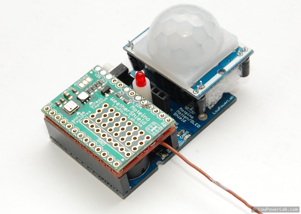
The first step was to solder the weather shield on top of the Moteino, only 7 pins are soldered after being raised a little: GND, VIN, 3.3, A7, A5, A4, A3. The bottom of the WeatherShield was insulated with a piece of electrical tape to avoid any shorts.

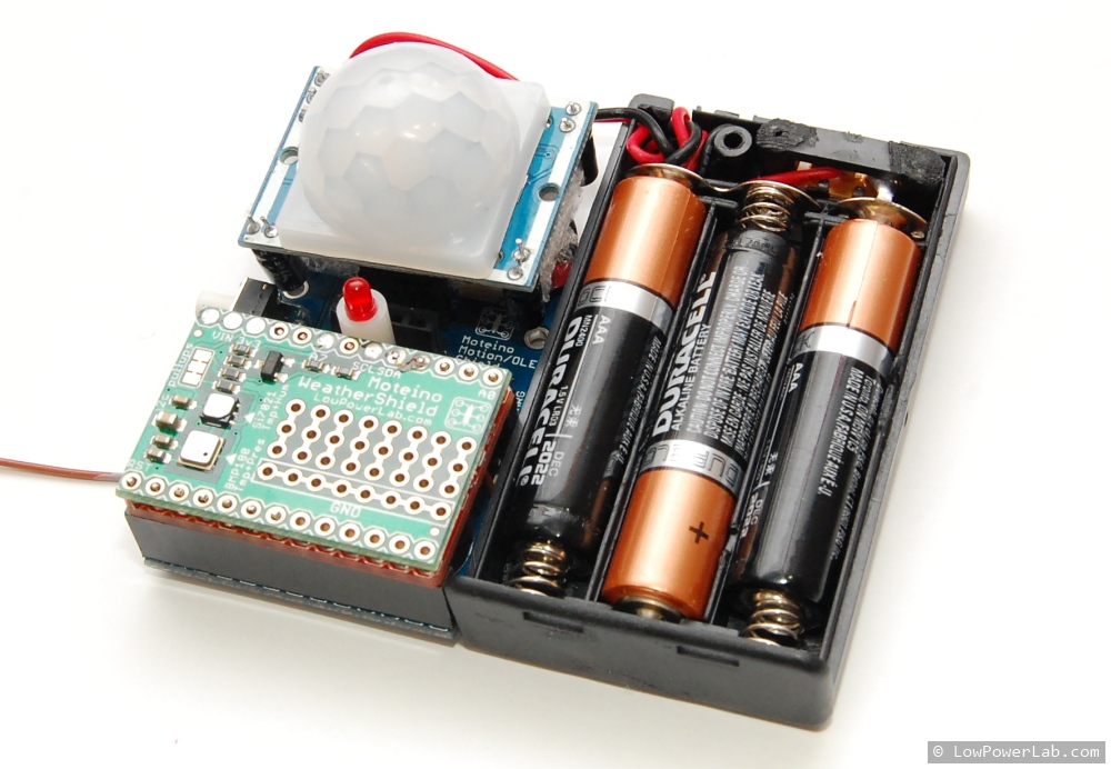
Then I added the new battery – a 3xAAA holder with older batteries. I needed 3x of them to get above 4V so there’s some head room for the voltage regulator on the Moteino and the PIR sensor which was modified to allow running into much lower voltages. I could have soldered the battery holder wires directly to the MotionMote PCB but I had some spare female JST connectors and I added that to make it easy to remove later if needed. I took the measurements to lasercut another box that will fit this.
With the help of previous box designs I was able to get the dimensions and hole alignments right the first try. The box blueprint is published here for those that might find it useful. Here’s everything after test fitting:

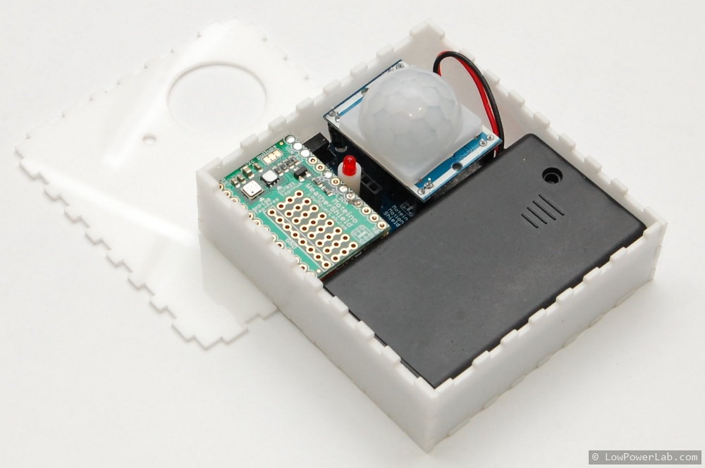
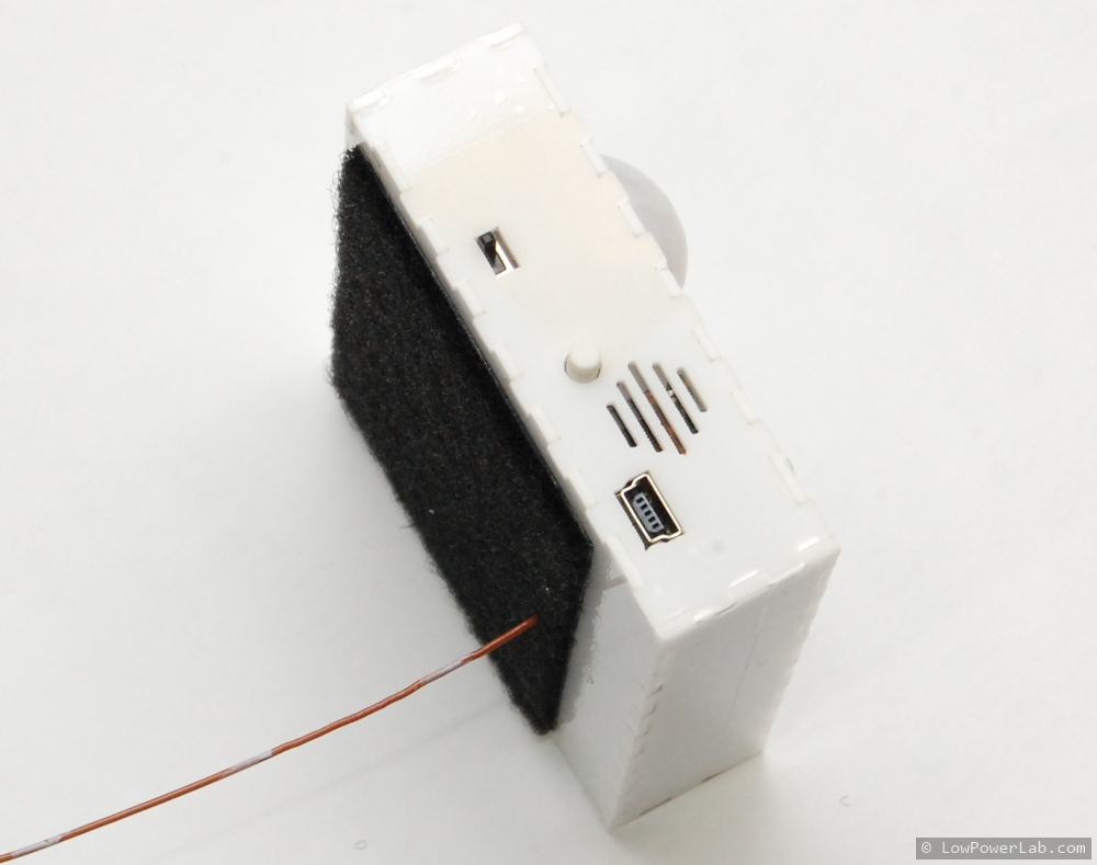
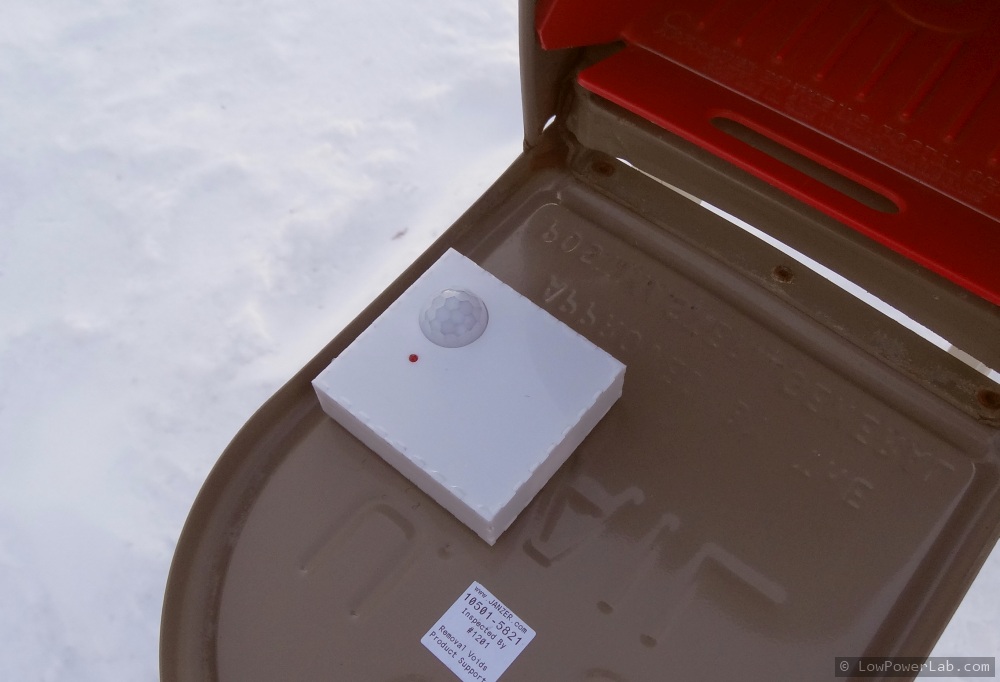
Velcro goes on the back and the Moteino antenna protrudes from a hole in the box through a short cut in the velcro. The wire antenna also goes out the mailbox through a tiny hole. The slots in the side allow air to go in for better humidity readings.
After some minimal coding, the mailbox notifier sketch is altered to do the WeatherShield readings. The new sketch is published in the same repo. The new mailbox is now smarter and it gives all the following readings:

LO:4h1m BAT:4.36v F:3475 H:37 P:29.32

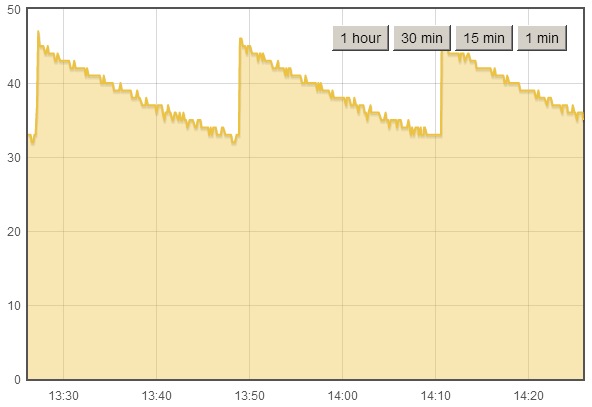
where LO is last open elapsed time,  F is fahrenheit in hundreds (divide by 100), H is humidity in %, and P is atmospheric pressure in inHg. It’s also running happy after being buried in the last winter storm. In the morning when the sun hits the mailbox directly the temperature can rise 20-30 degrees above the real temperature, but otherwise throughout the day it’s pretty stable and comparable to WeatherUnderground, when it’s overcast it’s often within 1 degree of WU but I am aware there are multiple factors that can influence a temperature reading in such a location. Humidity and pressure readings are also very stable and rise very deterministically.

Lasercut strip feeder for your pick & place

Got pick & place? Cool.
Got cut strips components but no strip feeders? No? Then this post is for you.

Problem: You need to assemble a small run of boards in your pick and place and buying full reels of parts makes no sense, instead you get a low count in cut strips. Strip feeders cost a lot, and they are not very special, just cold dumb metal. Of course, the manufacturer will sell you high quality feeders machined from aluminum/steel, but placing components from cut strips that already have pockets spaced evenly sounds like a very easy problem right? I mean you could just stick them on a cardboard with double sided tape and then teach the machine the first+last and it figures out the rest. That works but it’s a pain when you need to reload – you have to re-teach the machine since you won’t stick it exactly in the same place, you’re almost better off placing by hand.

Solution: So let’s make a strip feeder. I have lots of components that are less than a full reel (exotic resistors, transistors, crystals, caps, mosfets etc). Most of these are 8mm and 12mm tape, rarely 16mm. So it would be perfect to have a strip feeder that can be placed in a fixed position in the machine. To reload you just cut the pre-determined length, feed it through and align the first pocket to a marker on the side, reset component count for that row, and machine already knows where to continue, quick and easy. Continue reading

SwitchMote – one step closer to reality!

Just got another batch of SwitchMote and SwitchMote Shield PCBs from OSHPark the other day and I put one together for a test run. In the meantime Kris K has suggested I try another type of cover for SwitchMote. I think his idea was great and today I lasered a few of these covers that are meant to fit in the cutout of a regular rectangular light switch and they turned out very nice. This way people could replace the light switch and keep the original cover, or upgrade to a rectangular cutout cover (HomeDepot has all sorts of light switch covers, even paintable if you’d like to blend them with the wall color). The acrylic is also available in different colors from different sources but for now I’ll go with the usual white I’ve been using before.

The button caps come in different colors so I got a few samples to try out. I think blue, red, yellow and white should cover most needs. The green I found was pretty washed out, didn’t really like it, but I’ll keep looking. Here are a few build photos, and more in my flickr SwitchMote set:

More people started asking when this will be available. I’m already producing custom versions of this and I’m trying to get as much testing done as I can. It is mains power stuff so I’m taking this seriously. This 3rd prototype of SwitchMote includes a varistor and trace fuses for added safety against transients and overloads. I need to develop the firmware stack for this and think of how I want SwitchMotes to interact with each other. The SwitchMotes will need to be wirelessly re-programmable when the need arises so users would not have to disconnect it from the wall when they want to update it. But I want SwitchMote to be pretty autonomous. I will install and try a few on my own, planning on replacing some 3 way switches and some outside lights I’d like to turn ON/OFF from the master bedroom. Fingers x-ed. But so far so good, all the buttons work, the LEDs glow nicely in the dark and are very visible even from a distance, and mechanically the unit is pretty much where I want it to be. This setup should fit easily in any standard switch box.

Will follow up with details on progress, stay tuned!

Wishing a very Happy Holidays Merry Christmas and a Happy 2014 to everyone reading this blog!

So you can’t afford a $200 lightbox?

I’m going to try to break the blog silence with something worthwhile your precious reading time, my dear reader. There’s much to blog about and what’s going on at LowPowerLab but for now something simple.

I like to take nice pictures, it’s like giving candy to the eye. Because the images convey presentation. And good presentation is a paradigm of quality. Look at a good blog with crappy pictures – you will read but won’t be terribly impressed, right? Look at a less an average blog with great pictures and you will instantly follow it.

Until recently I took all the blog pictures on my white work desk but lately that’s gotten dirty from all the stuff I do on it but I’m too lazy to get everything off and add a coat of white paint, that’s for another day when I’m awfully bored. So I started using blank sheets of paper under the subject, that worked pretty nicely, but every shot took a few minutes to setup and get the right light and angle on the tripod so the light wouldn’t bounce too much off the ceiling etc, what a paaaain 8-( … OK – so looking around the web yields the typical results you will find on any product – cheapo lightboxes made of fabric, for around $30-$50, the nicer ones are $100-$200 or even more. I like to spend the extra buck on the nicer thing, but finding it impossible to spend that much on something as simple as a light box I thought – doh … how hard can it be to make one? Continue reading

Laminator dimmer hack for PCB or stencil toner transfer

This post will walk you through a dimmer enhanced laminator mod that allows an alternative method to transfer toner to PCBs or metal stencils.

The clothing iron transfer method works pretty well to make metal stencils. But for larger stencils it might not be so feasible, and a lot of people reported that they could not get a consistent transfer with their irons, maybe because not all behave the same. I have to say there can be lots of potential points of failure in this process. It’s a lot of trial and error, and my stencil tutorial was meant to help with eliminating some of those failures that I’ve gone through. I decided to try the laminator mod to see how that works compared to the iron. Continue reading

Reflow oven insulation

My reflow oven is very low tech. I haven’t modified it at all and even so I’ve been using it to reflow thousands of PCBs ever since LowPowerLab started.

It has top and bottom elements, but the heat does not distribute evenly, understandably so – you can see through it. Sometimes PCBs that were on the inside edge would take longer to reflow. Air escapes in several different places all over the oven enclosure, especially on the bottom front and back:

It’s time for a small improvement, adding some basic insulation in an attempt to stop air flow, keep the heat in and hopefully make it more evenly distributed. Continue reading

Mailbox notifier project upgrade

Time for an upgrade to my mailbox notifier. I long wanted to give it an upgrade and folks kept asking. Here are the things I wanted to change/add:

  • the transistor was a rather unnecessary complication and it made assembly more difficult. The hall sensor could simply be powered from a Moteino pin
  • a more weather proof enclosure would be nice
  • use more velcro to keep the thing from falling off (happened a few times when the mailman was more violent with my mailbox door).
  • how about battery voltage reading too!
  • upgrade code to use structs since all I’m sending is a bunch of integers
  • I wanted a standalone receiving unit with a LCD screen which I could operate from another 9V battery or just plug into an FTDI for quick reading. The other receiver on the RaspberryPi could still receive the same packets and still send an SMS

Clipboard01

Continue reading

Illustrated guide to making a simple solder paste application jig

DSC_0962_wFor a few months I used to tape scrap PCBs on my work desk and apply solder paste there. It was the quick no-brainer solution, but the more designs I had to assemble the more issues I started having with this method:

  • I could not accomodate more than 3-4 stencils at one time
  • it was pretty annoying to keep exchanging the stencils and rearrange the outer PCBs
  • it was taking a lot of space on my work desk even for only a few small stencils
  • Since everything was taped down, I would always have to be careful not to work in that area and bend/damage the stencils

So it was time to step up a little. I had some left over MDF material from making the workbench top plate, perfect for what I had in mind. I like quick solutions that return a lot on the little investment I make. Continue reading

Illustrated guide to making simple jigs for programming and testing

When I built the first revision of Moteino I had to come up with a way to program and test them quickly without having to solder the headers. I saw how others built complicated jigs for this purpose with all kinds of features, so I wasn’t very excited to do something like that.

It needed to be quick and simple (without the ‘dirty’) and also without a lot of waste – spring loaded test probes (aka pogo pins) are expensive and when revisions change sometimes the positions/function of the holes change as well and I didn’t want to spend a lot of time/$ making a jig. So I just stacked two of the same PCBs as the target and used pogo pins to hold the PCBs together (or rather the PCBs to hold the pins aligned and leveled). That worked great, with one hand I could hold/press the target PCB on top of the pogo pins, with the other do the programming.

So what are ‘pogo pins’?
They are small cylinders with a piston tensioned by a spring that pushes it out and they come in all sorts of lengths, thicknesses and tip configurations (they actually have codes for each tip type and length), a picture is better than words:

spring_loaded_test_probe_pogo_pin

Other PCBs required testing so I built quite a few such testing jigs, here are a few examples, notice the simplicity:

programming_jig_spring_loaded_test_probe_pogo_pin

The rest of this blog entry is a guide to making jigs like these. Your final solution and it’s capabilities is only limited by your imagination. For instance you might test if a pin goes high by soldering an LED, or turn a pin HIGH/LOW by soldering a switch.

Continue reading

Sump pump alert with Moteino & HC-SR04

UPDATE: This project has been replaced/updated with SonarMote. See this blog post for a more rencent implementation of what you see here. The alerts are now implemented as simple events on the Moteino Gateway.

Here’s another project I wanted to do for a long time. I wanted a sump pump flood warning alert system in place, for peace of mind when I’m gone from home for prolonged periods. For whatever reason I thought this was going to be more difficult but no, it’s almost as easy as pie!

All I needed was a HC-SR04 sonar sensor and a USB 5V wall supply. The sensor only works at 5V so this method of powering the Moteino was very convenient since I already have an outlet close by for the sump pump.

The sensor has 4 pins clearly marked: VCC, GND, TRIG and ECHO. I connected VCC to VIN on Moteino, ECHO goes to D3 and TRIG to D4.

Moteino_HC-SR04_SumpPumpAlert

I used some of the code this instructable to get started and added my wireless code to handle packets and blink the LED and was done in no time. The setup was very simple, I estimated a good spot underneath the sump pump cover where there are no obstructions inside, cleaned it up, taped some velcro, secured the wires and that was pretty much it.

 Moteino_HC-SR04_SumpPumpAlert_cover Moteino_HC-SR04_SumpPumpAlert_installed

I added a few lines of code to my main Python script running on the RaspberryPi.
By the way, here’s how my RaspberryPi setup looks like, including the ATXRaspi power controller, the power button and the gateway Moteino (it’s an older R1 but just as good for as a gateway):

Moteino_RaspberryPi_ATXRaspi_PowerButton

The Python script logs the data to EmonCMS and here’s a graph of how that looks like, the Moteino reports the distance to the water surface, so the spikes means the sump pump just kicked ON, and as water rises the distance decreases until the pump starts again:

EmonCMS_SumpPump

It’s been a rainy spring so far here and I knew my pump kicks ON quite often, now I can see it in real time, and setup alerts if the water rises too much. Seems like the pump is always pumping water out when it rises to 32cm below basement surface. So setting an alert to something like 20cm below surface should be enough since I don’t expect the water to ever rise so much as long as the pump works. The alert code will send me a SMS message when this happens, here’s a test level, I set the live value at 20cm:

Moteino_HC-SR04_SumpPumpAlert_SMS

You can of course setup other types of alerts – like audio alerts or maybe a LED visual indicator (less useful when you’re not in your basement).

Fun/Scary fact: The sensor is very accurate even though there’s a variance of 1cm between some readings (resulting in a sawtooth graph) as water rises. Based on the graphs, how often the water is pumped (every ~23 minutes), and how big the reservoir is, I figured my sump pump removes roughly about 18.5 liters every cycle, or about 1158 liters (306 gal) every day, wow!

So now there’s an extra level of peace of mind when I leave on vacation. I guess being gone for even 1 day could mean disaster if the sump pump breaks down at the same time!

Time to think about how to gather/store all that water instead of throwing it away, after all, I pay something like $11 for every 1000 gallons of city water.

Source code is on GitHub: https://github.com/LowPowerLab/SumpPumpAlert