
CurrentRanger is now at revision R3!

I received great feedback and several threads in the forum outlined some patterns of user behavior which led me to make some improvements and hopefully eliminate some of the issues I’ve seen people run into. Here is the change log:
Reverse polarity protection
Perhaps some folks were too excited to turn the CurrentRanger on and missed double checking their battery polarity and pufff .. the charger chip released the smoke. I offered free fix/repair to a few who’ve asked, and to put this behind – R3 now ships with reverse polarity protection. If you get it wrong, nothing happens, including the obvious – won’t turn on!
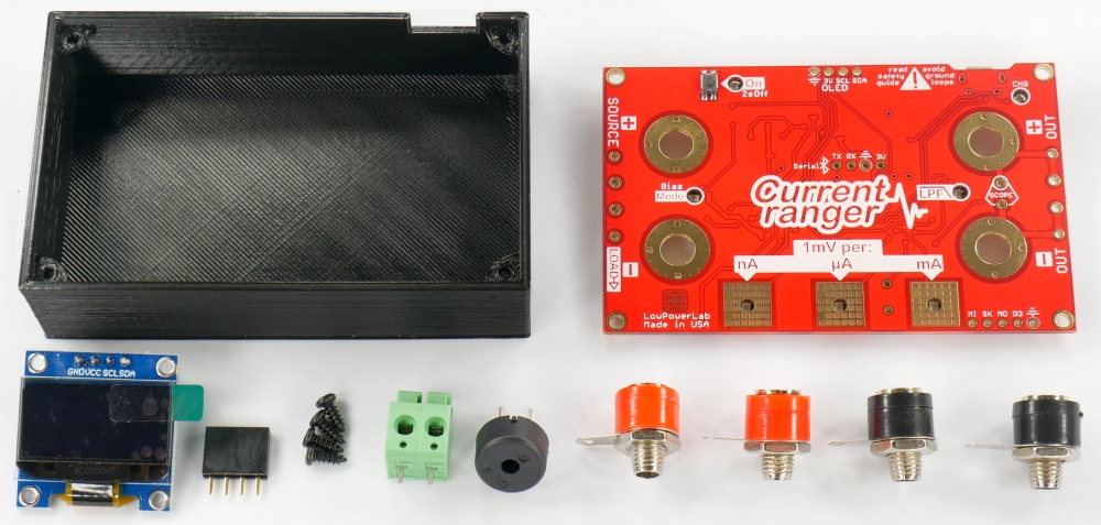
Redesigned 3D enclosure
The previous pillar style enclosure takes about 1h05m to print. And because of the way the mounting pillars are placed in R1-R2 the case called for PETG (stronger less brittle material) but often produced diagonal drag lines in the inside-bottom of the case, and PET tends to print stringy which requires additional cleanup. Mounting screws are now moved closer to corners, this yields more PCB area and allows the case to have top corner posts which are a lot more practical, free the bottom of the case for a larger battery and shave a whopping 18 minutes off the print time. This also yields more room for enclosing a bluetooth module inside the case while keeping the case low profile. And the case print just looks that much better in PLA (no posts that can easily snap either). I’m really happy about this improvement.
Gold terminals be gone!
I am done with Gold terminals, they are the fake news of banana terminals. There is nothing truly gold about them. I tried to like them but frankly, I found them to be more trouble than their gold appearance is worth. Being exposed makes them a short hazard, and twist-locking wiring actually rips the wires. Besides, I almost never use the input terminals since I added the green thumb terminal which makes it a snap to insert battery and project wires. Those gold terminals looked rich and fancy (until the “gold” wears off revealing the dull communist metal) and that’s where the “goods” stop. And yes – I did try many different vendors, I could not find a vendor with consistent quality and repeatability. They may be good for your speaker where you never touch and see them again, but I think not suitable for an electronic instrument.

You want Gold(less) terminals on your CurrentRanger? Be my guest, get them from wherever you can, but I won’t ship these anymore. I cant put fake on awesome. Instead the kit is now standard with low profile banana terminals – simple, compact, functional, consistent, just as or more conductive, that’s real “gold” in my e-tool box.
Moved components & features
A few folks in the forum reported damaging/snapping some of the capacitors near the input terminals, causing the unit to behave erratically – these are now moved away from the terminals to help reduce the chance of this happening. Just to give you an idea, here’s what that looked like, and what to avoid doing when mounting mechanicals around small SMD components on any board:

Misc other changes & additions:
- the power button is moved slightly left to allow easier access when OLED is mounted
- the charge LED is now moved next to the USB and is see-through just like all other board LEDs
- the Bias LED is moved symmetrical to the LPF LED
- a GND pin added to the SPI header next to the lower right mounting hole
- minor layout changes & silkscreen additions
Silkscreen nightmares!
Since the top of the PCB serves as the user interface, the silkscreen needs to look fairly good and crisp. I went the extra mile to try and design some nice graphics and make a PCB with a bunch of traces look more attractive and professional.
Unfortunately since inception I’ve had numerous silkscreen issues because of these graphic elements (some my fault, some the fab’s fault, and some “in between”) causing several batches of panels to go straight into the trash. I painstakingly retraced all these graphic elements on the board in a vectorized form and these issues are now resolved (as far as silkscreen design goes). The fab can still screw up but hopefully that won’t happen again.
The official guide is updated, as always please read it carefully before using your unit. Here’s the SMD side:

CurrentRanger is made with great love and pride in Michigan USA, and I welcome feedback, suggestions and contributions.
Hello, this measurement tool seems to be really good. I would be very interested abbout the highest possible measurement speed. I saw in the SW sources, that the ADC sampling speed is set to slow.
When the sampling speed is set to the fastest, which sampling time is reachable and can the data still be send out using USB?
Is it possible to make the autorange faster?
What are your experiences?
Best regards
geer
It’s possible to go faster. How fast is limited by the ADC speed and also how fast we can loop and do the ADC reading while also updating the OLED and check other things. The faster the ADC is the less averaging it will have and hence more noise. It is a tradeoff, and I came up with a set of “speeds” that seem to work well and the user can choose and experiment with. Beyond that, the source code is available and not too hard to change the ADC behavior. The auto-range speed is also mostly dependent on the ADC speed. In my use and from feedback it seems the current speed is quite sufficient for most everything.
Thanks, please look for my email.