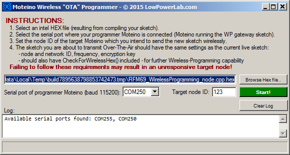
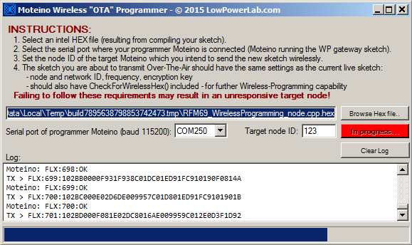
Not much to it really, a mere 300 lines of loosely written code, last (mid)night. Here’s a rundown of the features, I tried to make this a bit more useful and intuitive to use than the command line python script, so that would be the main attraction other than being a GUI:
gives you a list of available serial ports so you don’t have to guess (you still have to know which serial port your wireless programmer Moteino is connected to)
allows you to type/paste or browse for a hex file
allows a numeric target node ID
once all settings are populated with valid info, the Start! button is enabled
upon exit, it saves the settings to registry and attempts to read them back in future launches
Clicking Start! will do some validation and start the OTA protocol just as the python script did it, but also gives you more visual feedback with a progress bar at the bottom:
I will potentially expand this to allow remote wireless programming through a tcp port, just like the 3rd party vb6 app, but I doubt that will be very popular so I am sticking to the basics for now. If there are any bugs let me know.
This is it for 2015, see you on the other side of 2016!
Revision R2 of MightyHat is now available. Since the changes are not very significant I debated whether this should be really a R1.1 but I don’t like minor revision numbers so I went with R2. Basically it just adds the following main features:
Battery power switch – this is a slide switch that can cutoff the battery. During my many hours of testing, it occurred it would be useful to just have an onboard battery switch instead of pulling it in and out. Also if you have the battery tucked tight underneath the board it’s not always really easy to pull the JST connector. Or say if you want to ship a complete Pi+MightyHat+Battery inside an enclosure and don’t want to have it powered up. A side switch is convenient for this purpose: If you don’t want the switch then there is a solder jumper behind it which you will need to solder-bridge if you are using a backup battery.
Two momentary tactile buttons tied to the remaining available I2C pins which were previously unused (A4 and A5). These will be general purpose buttons to do whatever you like. If you want you can build some menu interaction for the LCD or whatever else. They connect GND to A4 and A5 and the pins should be declared as INPUT_PULLUP. The provided kit buttons have long actuators that rise just above the main power button (to allow pressing them when enclosed), but you could otherwise solder any standard 6mm tactile buttons here.
A few power path optimizations and tweaks.
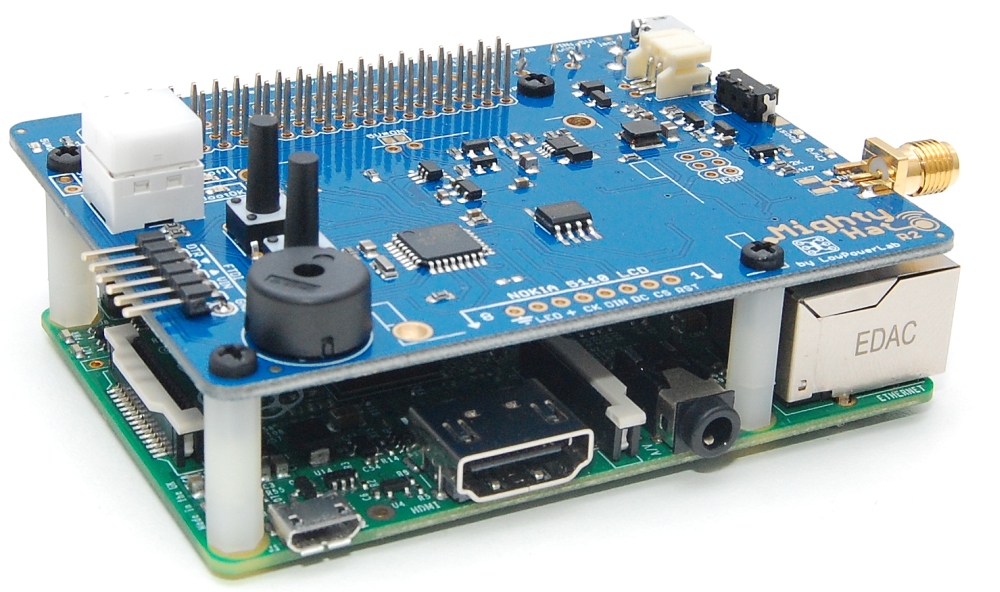
I sourced RP-SMA connectors which seem to be a lot more popular than SMA (shown in photo below – note male pin in the center).
Besides the new positions/cutouts of the buttons and switch all other physical features remain at the same positions as R1.
I have an enclosure close to finalizing so maybe I will post that when it’s ready for those who’d like to lasercut their own case. I played around with 1/8″ and 1/16″ acrylic and finally settled on 1/8″ because it’s more dimensionally stable and makes for a sturdier case. The thin 1/16″ was light but it was prone to breaking where holes were very close to the edge or between USB/Ethernet connectors. Here are a few snapshots of R2:
Wondering what it takes to put together a kit with all the necessary parts to make a completely functional piece of hardware like this? Consider these facts:
The PCB board has some 62 SMD parts on it after picking and placing.
Some 13 more through hole parts (and the SMD transceiver) are required to be sourced and soldered separately (some optional like the LCD, buzzer or SMA connector).
To make a nice tight fit while avoiding any shorts or touching ontop of the Pi, an optimal height of 17mm is required between the Pi and MightyHat. Standoff combinations were sourced to achieve this height since 17mm is not standard or easy to find stanoff height.
Add a 1-cell 3.7v Lithium Polymer battery (optional) to act as a UPS and you are golden. I recommend this 2Ah battery from Adafruit which has decent capacity and attaches nicely with velcro under the Hat.
Total height of the Pi+MightyHat with all options installed is just 32mm (about 40mm when enclosed with 1/8″/3mm acrylic).
Finally I need to mention I have made numerous tweaks and improvements to the RFM69 gateway sample sketch for the MightyHat. I added a bunch of defines that make it easy to disable the LCD, wireless programming, or Automatic Transmission Control. Besides making the sketch a lot smaller (LCD has the largest footprint because of fonts and graphics), it allows running your gateway without an LCD:
Check out this video from John (his youtube channel here) who implemented a custom home automation system of his own, based on my gateway solution. He has done a little script editing to augment and add to the functionality (new metrics and events) already given via metrics.js. I am looking forward to see more of the details of his implementation and especially the hardware. He mentioned something cool which I initially envisioned as a use case when I designed the hardware but never implemented this feature on my own SwitchMotes: using the unused status LEDs (and button?) of a SwitchMote to display the status of his GarageMote. He also added a sonar sensor to his garage mote to detect whether there is a car parked or not, this could be a really cool addition to a GarageMote. The video also gives an overview of how the gateway and end nodes interact. If John will create more follow up content I will post it wherever appropriate. Thanks John for sharing this!
The Moteino Framework Gateway software stack was updated to V7 and new sources are available at their Github repo, and also a new debian-wheezy image with the changes is released (for the image link see the Gateway image page). This release addresses some bugs and adds some significant refactoring and moving of directories. Most importantly the gateway application is now residing in /home/pi/gateway along with the public www directory for ease and more consistency (previously in /home/pi/moteino). Here are the other changes that go with this:
the www directory is moved from /var/www/default to /home/pi/gateway/www
the .htpasswd file and ssl certificate files are now in /home/pi/gateway/data/secure
the database files and log data are now kept in /home/pi/gateway/data/db
nconf is used to manage the settings file (previously known as settings.js, it was using straight nodejs exports to import the settings) which is now named settings.json5 and is a JSON5 based (via json5 package) settings file which can be manually edited as well as maintained through the app (in a future release)
there is a new package.json file which includes all the node dependencies. If you’re inclined to manually install the software stack, now all you have to do is cd /home/pi/gateway and npm install to get all these dependencies installed
I have watched how the internet has gone wild with the introduction of the ESP8266, 2.4ghz wifi modules. They are (dirt chinese) cheap, have lots of output power, were hailed as the new backbone and de-facto standard of the so called “Internet Of Things” with their “long range”, high wifi bitrates, no need for a gateway, simple AT command set, and are promoted as the what-else-could-you-ask-for by the big wigs of the online IoT/hacker community. There has been loads of development pouring into these chips. You can upload to them directly from your beloved Arduino IDE, they have loads of memory compared to an Arduino. You can run a webserver on them and control things with their GPIO, great. Look, if you hack around a little you can even sleep them at 78uA, so low power – amazing. I even bought a few to try out for myself.
Some reality-check and practical use reveals they are ideal in some cases and not so much in others. If you want a quick snap wifi enabled device that blinks a led or whatever at 54mbps (million blinks per second) or pushes temperature directly into the cloud, they will make great projects for a bunch of permanently powered nodes. The biggest problem I see is their not so low power consumption. I don’t care how deep you can put it to sleep, the wifi protocol will never be low power enough, not even close (neither bluetooth or BLE which also won’t have the range). The wakeup and pairing of wifi alone can be several seconds of power hungry consumption. The ESP8266’s current peaks can be in excess of 200mA at max TX power and we know that even short current peaks drain a battery much faster than small longer current peaks. All this matters when you are on a limited power budget or a small battery that won’t take power spikes very well.
If you spend any amount of time reading application notes and technical documentation about wireless RF technologies from companies like TI or others who have excellent knowledge bases, you will immediately get a sense of how imperative the need to reduce transmission and reception current. They invest massive amounts of R&D to decrease any kind of current and the time spent in receiving and transmitting. Spikes are especially regarded as undesirable culprits. When they reach the limits of squeezing that least bit of uptime they invest in creating ways of reducing the duty cycling of reception and transmission by different modulation schemes so that reception can be had at a lower mean consumption rate, and reception rate is overall more successful (selectivity, blocking and immunity means more accurate reception and immunity to the ever increasing RF noise and consequently requires less transmissions which saves more current). In the wifi world we can’t really talk about that because the protocol was not specifically created for low power applications.
Let’s talk range and why you’d ever want to go with sub 1-Ghz radios. We know that the lower the bandwidth and bitrate the higher the sensitivity and consequently longer the range (it’s like a very narrow piece of the spectrum where the radios spell out each word, the slower the spelling the lesser the chance the receiver will miss or missunderstand any part of the message). Also the lower the frequency bands the higher penetration of the medium, it’s just physics. I think the following video from TI really summarizes it all and why Sub 1-Ghz technology will always be superior in several ways.
Anyone remember CC3000? What ever happened to the other wifi radios like CC3000 series which were the ex de-facto IoT about 2 years ago? Yup they were expensive and the ESP8266 with it’s ridiculous $2 price tag totally killed it right there. Actually I just did a quick search for ESP8266 and the prices I see are more like $7-15 depending where you shop, add an Arduino and you’re not saving for that lunch burger any more. To get the $2-3 price you have to buy from china direct (ebay, alibaba etc) so if you want to wait about a month and buy a pairing $2 arduino while you’re there, you can still save enough to enjoy a yummy burger.
Anyway, as I always have since their introduction, for some reason I cannot seem to be impressed no matter how many cool ESP powered projects I read about, and I keep wanting to find an application where they would be a better match than sub-ghz, but I have yet to find one. My humble Moteinos (right, which are not made in china and don’t cost $2 and won’t save you a burger so they are more healthy 🙂 ) still work for anything and everything wireless/remote control applications. I don’t need 54mbps for turning on a light, checking my sump pump, opening my garage or reporting motion. Neither do utilities and industrial integrators who always seem to prefer sub ghz technology for their meters and applications.
For those who feel this was unfair or inaccurate and want to start a debate please note I did not meant to compare Moteino to ESP8266, they are completely different in every way.
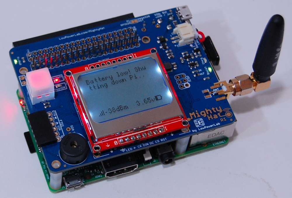
I’m pleased to introduce a new development and product that I have been working on in the past months: MightyHat !
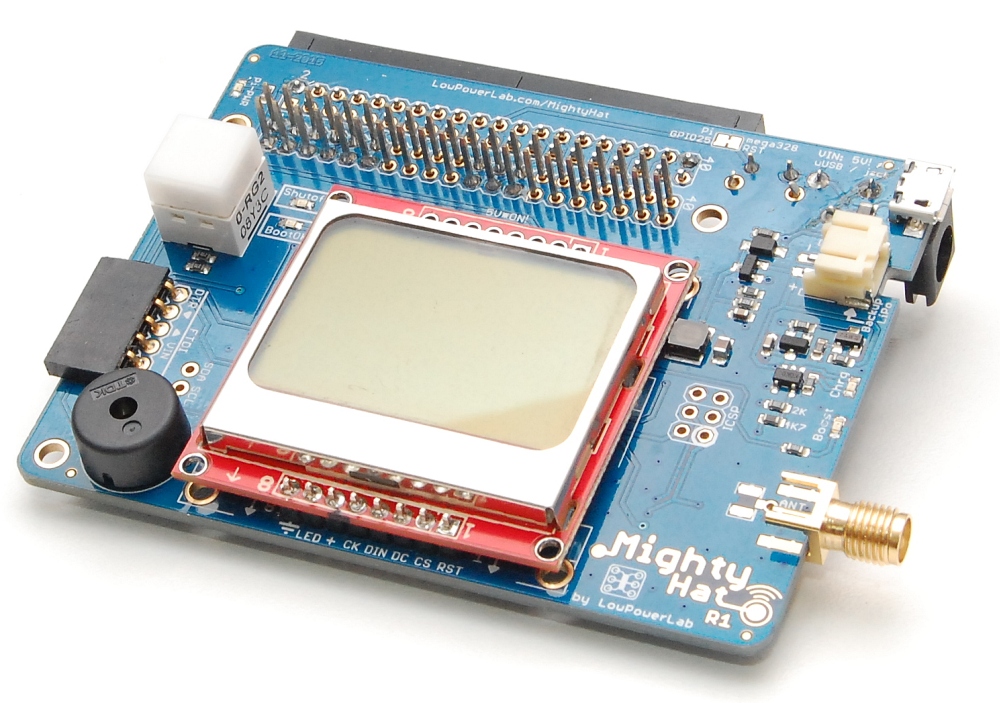
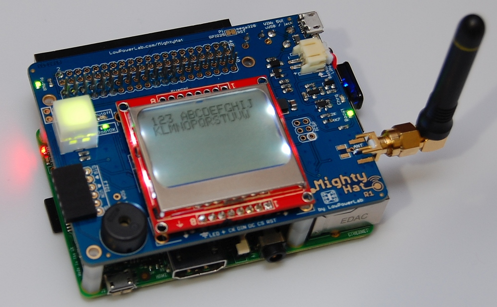
It’s my first RaspberryPi hat and it it primarily meant to serve as an easy to deploy gateway for the Moteino Framework of wireless devices. It is a combination of ATXRaspi and MightyBoost with a bunch of other features that I long envisioned would be nice to have in such a gateway. Here’s a rundown of that:
atmega328p @ 16mhz, 3.3v interfacing with the Pi via seveal GPIO: 2 for the power control (similar to ATXRaspi), 2 for serial (TX, RX), and a pin to RST the atmega328p
ability to program it via FTDI header (when Pi is off), from the Pi with avrdude (when the Pi is running), and wirelessly through Moteino’s Wireless Programming capability
optional Nokia 5110 84x48px backlit monochrome LCD for anything you want to display, the sample sketch will make use of this, see below for link. This is a great LCD alternative to the 2×20 character LCD I’ve been using before, and cheaper/more common too, and with the great u8glib font support, you can fit really long messages on the screen
optional battery (standard 1 cell Lithium Polymer, 2Ah+ recommended) backup can be hot plugged in any time if you want to have backup power. It will also run without a battery without any issues. While plugged, the charging circuit is activated and will charge the battery if external power is present. If external power is lost the battery kicks in to keep your Pi running. The included sample sketch has a voltage threshold that once reached will trigger the Pi to shutdown cleanly
Fun fact: a 2000mAh battery will run a typical setup like the one below (Pi B+, wifi dongle, MightyHat + active atmega328p + RFM69HW + LCD) for about 3 hours before it will shutdown the Pi when the battery reaches a low voltage threshold:
external power is conveniently provided through the usual micro USB or 2.1mm jack
included red/green button makes for a nice power button that will control power to the Pi through the GPIO header and a power path that includes a 5V booster (similar to MightyBoost). The power path to the Pi is latched so that regardless if the atmega328p is reset, the power to the Pi is uninterrupted (as long as USB or battery is plugged in). This makes it possible to reprogram the atmega328p at any time, even directly from the Pi as I will show in a future walkthrough
allow RFM69W/HW and LoRa RFM95/96 transceivers to a wide range of low power and long range RF applications
the Pi GPIO is doubled to the top of the board where you can solder headers to bring it to the side. The included headers will also protrude and make all pins accessible on top of the PCB already
buzzer if you want to get creative with beeps/alerts
SMA footprint allows soldering SMA connectors for more aesthetic/commercial looking antennas if you mind the usual wire monopole antenna
compact design brings all essential ports to one side (where USB/ethernet is) while allowing easy access to all secondary ports (HDMI, audio, SD card access, etc)
A forum user has raised a question about his BellMote which was not working and as a result I realized that I might have shipped some BellMote kits without fixing a PCB glitch that I had on that batch of PCBs. Namely there was a trace missing on the PCB, which can be fixed by soldering a short hookup wire between these 2 points (red wire shown):
So my apologies for missing that in some kits. If you have one I would hope you are able to add the missing wire, or I can do it for you and I can test the BellMote to ensure it’s working if you’d like to return it “for service”. I guess they call that a recall in the auto world. Feel free to contact me if you have questions or concerns about this specific issue.
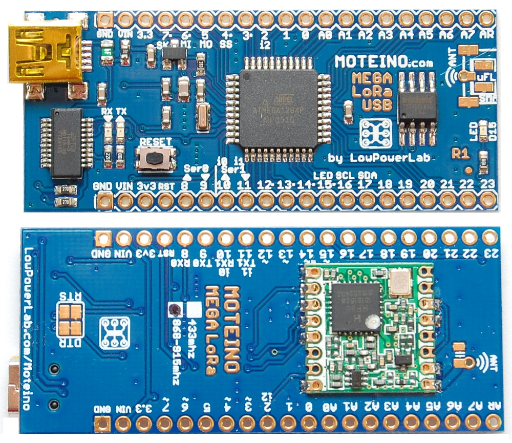
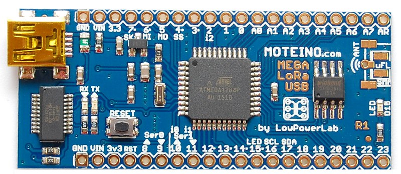
There is a new variant of Moteino available: MoteinoMEGA with LoRa footprint and onboard FTDI USB-serial converter. This is the first MEGA USB variant. It will also work with RFM69HCW radios if you want a MEGA-USB with RFM69, but for now you will need to source your RFM69HCW from somewhere else. Otherwise all sketches and examples should work as before. I have yet to create a pinout diagram for this variant but it’s pretty much the same as the MoteinoMEGA. Here is a shot of both sides, shown with a RFM95 LoRa transceiver soldered on the bottom:
For the past few years I’ve been using this XTRONIC 6000 series solder station which cost around $120 and I picked it because it was compact and it included hot air which was always very useful for SMD reworking. I (ab)used it and it soldered many thousands of parts at Low Power Lab. Needless to say, you always get what you pay for. The iron, would take about 1 minute to be ready for work, and for lead-free soldering I would always keep it at the maximum 480 degrees (Celsius?) and it would still take forever to heat up joints that have lots of metal mass or are part of a GND pour. And the tip being always on, it would gradually deteriorate and would need changing from time to time. But hey, for the money I spent, I think it paid for itself many times over.
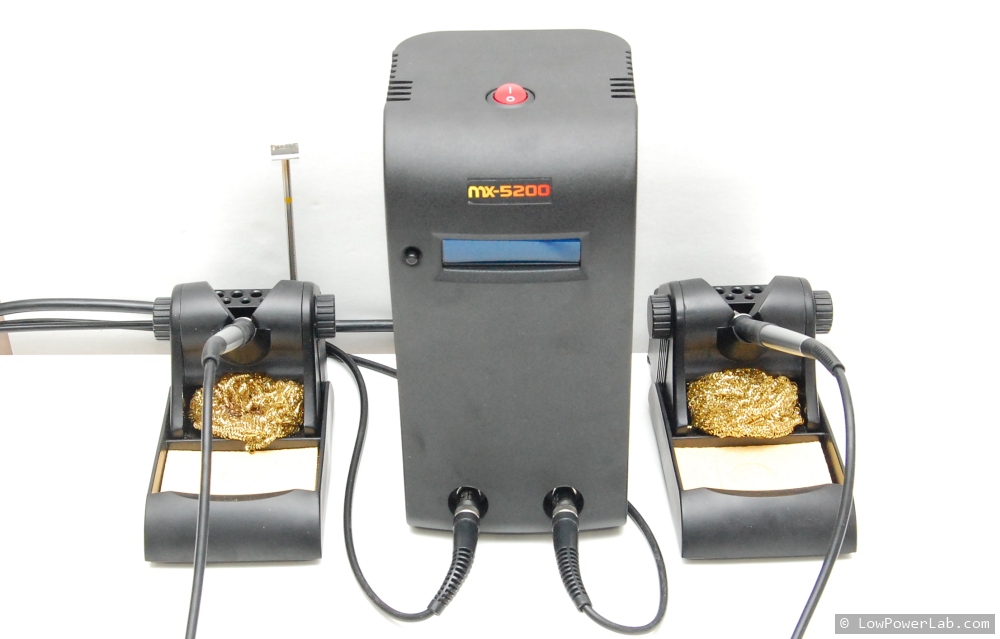
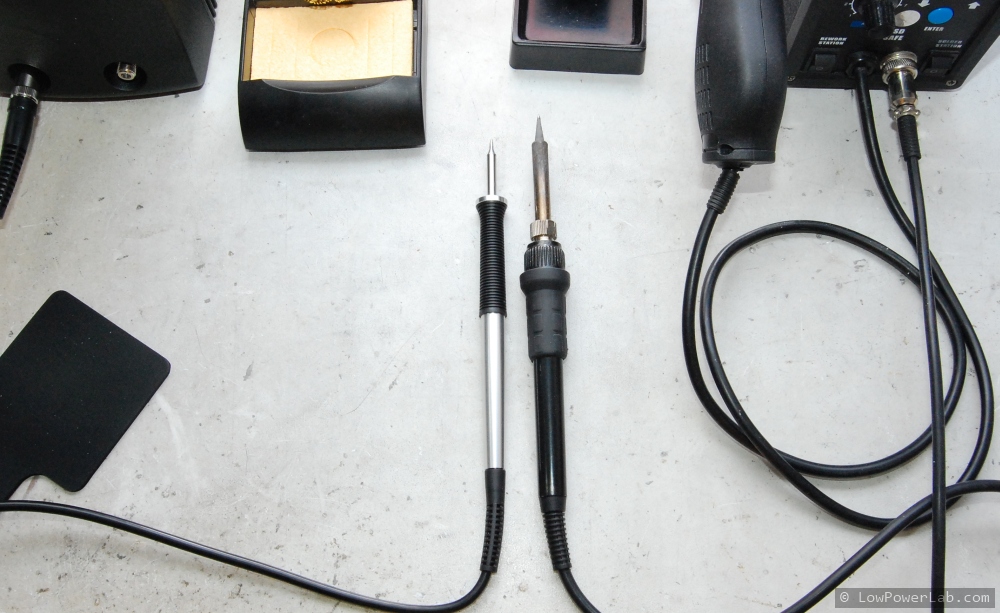
So … it’s time for an early Christmas solder station upgrade. I know METCAL is the way to go and the obvious choice was the MX-5200 Smart Heat System which allows 2 independent outputs. Since this particular kit only includes the hand pieces and stands, and not any tips, I bundled some of these lead-free tips (STTC-125) and also two wide blade tips for easy desoldering of wide packages (for effortless removing of radios from Moteinos). These blades alone cost more than my previous station, doh. One mistake I made in my initial order was I ordered the wrong tips for lead-free (STTC-525) and although they claim to be “lead free compatible” they would not melt lead-free solder. When all was said and done, this came to around $1200, but was it worth it? I wanted to write about this upgrade and share my experience.
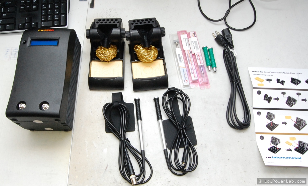
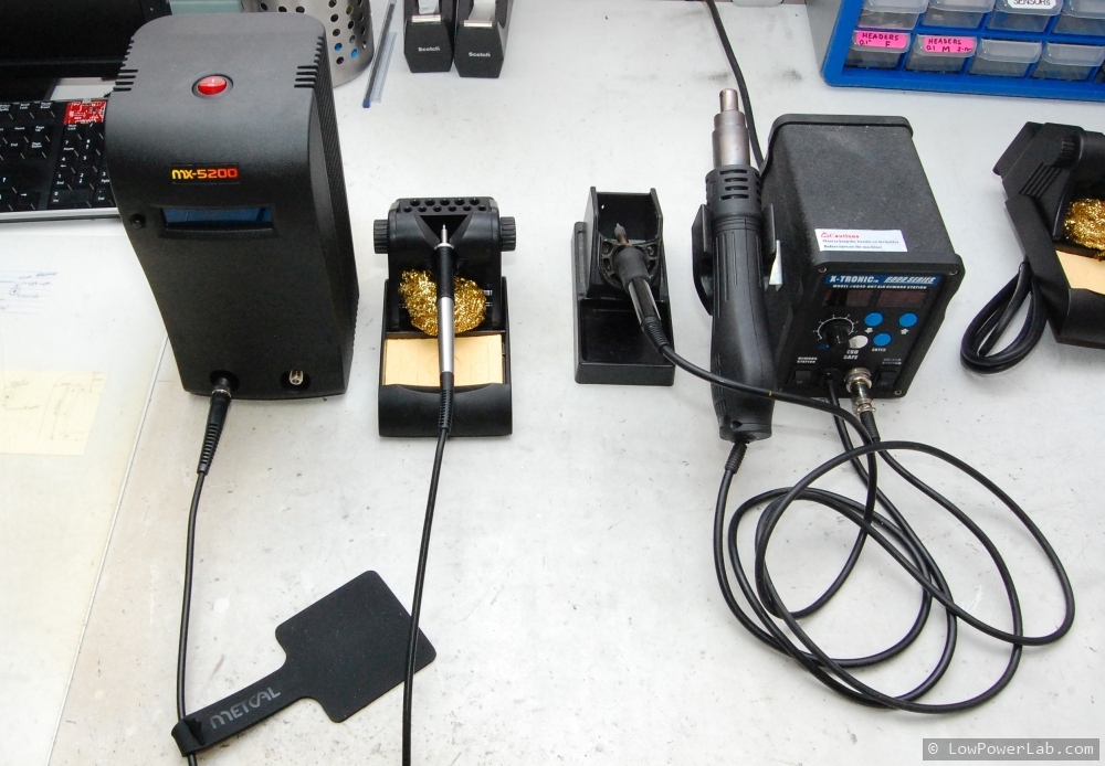
Here’s a shot of the unboxing and compared to the old station – which I will keep for the hot air.
I’ve used the METCAL station for about 2 weeks and if there was 1 word to describe it … I would choose “amazing”. It feels like I just took a giant leap. It just works and it makes you love it every time you use it. Yeah it’s pricey but when it gives you that almost instant endless heat and makes your solder job go fast and flawless, you start to appreciate the price tag. I won’t do a teardown to bore everyone (do people still watch 1 hour long teardowns?) and it might void the 5 year warranty. There’s a great video walkthrough below that I think is well made and to-the-point and illustrates the essentials and capabilities of this tool:
To summarize, here’s what I love about this tool (just about everything):
it heats up FAAAAAAST!
melts any solder joint instantly, even those large GNDs are effortlessly melted, no more soldering frustration. The LORA modules used to be a bit of a pain to solder because their GND pads were part of the GND pour with no thermal relief, with the METCAL they solder as fast as any other pad
hand pieces connectors go in and out the station ports without the need to tighten the optional nut
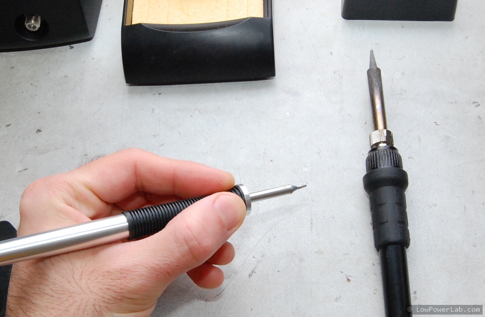
hand pieces are so light they feel like a pen, and your hand is very close to the working spot, making it feel up close and giving your hand more precision:
there are no dials, no temperature selection or anything like that, just turn it ON and it takes care of the rest. It sends just enough heat to do the job and when it feels there’s more heat needed it spikes more energy to that particular port. It’s called “Smart Heat” after all and it seems to do a great job.
there is a single button that just selects between LEFT, RIGHT or BOTH ports, this way you can have both plugged in, and only heat the one you need, then switch, or use both when you need to rework something.
when seated in the rests, the heat is minimized to help preserve the tip.
“plug and play” hot swap tips … they plug in and out effortlessly with the included rubber pads. The station detects when a tip is removed and plugged back in and only applies heat appropriately.
the station is very hefty and solidly built, doesn’t have that flimsy plasticky cheap feel to it, this is not a toy.
has many other accesories and hand pieces that go with it for a complete soldering/desoldering/rework lineup.
Expensive tools are always hard to justify, some people like to say. But I argue they are in fact FREE. Read on. They are hard to justify unless you use them every day. Then you want the best you can get so that the tool doesn’t stand in the way of your work. Just saving 10 seconds a solder job will add up to several hours in a year. If your time is worth anything, then a tool like this will pay itself within just 1 year, in time and neurons saved. After that it becomes free. See how expensive tools are actually free?
Enough already, I think I made my case. This tool is awesome, if you got the budget or long planned to, get it, today, you will love it. It will give you pleasure to work with this tool, and step you up that professional ladder. Plus it’s the kind of tool that lasts a lifetime, well worth the investment.
There is now a new extension to the RFM69 library. It’s called RFM69_ATC aka Automatic Transmission Control. Many thanks to Tom Studwell who implemented this and shared it in the forum. The basic idea behind this extension is to allow your nodes to dial down transmission power based on the received signal strength indicator (RSSI). For instance a sleepy battery node like a MotionMote sits still inside the home and usually has a very strong received signal, somewhere in the range of -30 to -40dBm when transmitting at full power. You could manually tune that down using radio.setPowerLevel(..) in code but its tedious and is a static change, if you move the node or conditions change it will not be smart to adjust the power level to the new environment. However with RFM69_ATC this is done automatically for you, you just need to indicate a target RSSI. On each packet sent and ACK received (using sendWithRetry(…) is required), the node analyzes the actual RSSI and continuously adjusts its own transmission power level of the RFM69 transceiver to attempt to match the target RSSI (+ or -). This way that end node is only “loud” enough to be heard by the gateway, not much louder. Close by nodes can “whisper” while nodes farther away or with more obstacles will “speak up” as necessary but avoid that default fixed maximum “screaming” level. This is “polite” in terms of “RF pollution” and efficient in terms of power consumption. Even non-battery nodes where power is no problem should implement this for the sake of the “polite” factor.
I have updated the Node and Gateway examples to have ATC enabled, and also the MotionMote example is now ATC enabled, in this case with a target RSSI of -90dBm. The noise floor is somewhere around -100dBm with the default RFM69 lib settings, so for static nodes that won’t experience a lot of movement or temperature drifts, a -90dBm target is pretty safe. That will keep the transmitter power to a minimum and save power. We know that the greatest toll on a battery powered node are the spikes of current used when the transmitter is active (up to 130mA for RFM69HW). Reducing the transmit power level to the minimum required will exponentially reduce that spike and result in longer battery life and a more “quiet” sensor network that won’t reach across your whole neighborhood. This is really awesome!
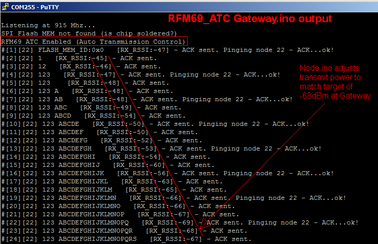
Here is a sample transmission using the Gateway and Node examples linked above. Note how the node starts transmitting at full power, then dials down power to match a test RSSI target of -68dBm. This is output from the Gateway end:
There are a few required changes to a sketch where you want to use ATC:
you must #include<RFM69_ATC.h>in addition to #include <RFM69.h>
you must use RFM69_ATC radio; instead of RFM69 radio;
for the gateway/receiver end the above two changes are sufficient, for the end node that does the power level adjustment you must also do the following:
in your setup() function (after all RFM69 initialization is complete) call this function to set your target RSSI: radio.enableAutoPower(targetRSSI);
targetRSSI is a negative integer, should be from very strong (-30) to very weak (-95). Usually you would want to be closer to the noise floor end (-100) since you want to reduce transmit power to the bare minimum
this is a one time call that enables the dynamic adjustment of the output power on that node
you must use radio.sendWithRetry() instead of just radio.send() or a combination of radio.send() and radio.receiveDone() for the radio to be able to receive the important headers from the gateway that tells it how to handle its power, this was done in the MotionMote example linked above
Once these changes are implemented, the node will start to progressively dial down power (assuming it starts transmitting at full power) with each packet sent, until the RSSI meets the target. When the RSSI is below the target power is dialed up again and so on, in an attempt to stay as close to the target as possible.
In the examples that I mentioned there is a pattern that I followed by implementing a define directive (#define ENABLE_ATC) which when left uncommented will enable ATC at compile time, if removed/commented the sketch will run normally without ATC. As always, bug reports, suggestions and contributions are welcome, the forum is the best place for that purpose.
I must mention here that at this time I have only partially implemented his variant with some adjustments to Tom’s implementation (I left the differences commented out in my version). For now I chose to leave my power control resolution as is. He actually went into more detail allowing a finer control of the power control – this is because of the differences between RFM69W and HW which handle output power control differently. If you’d like to try his variant with that extra control check this forum post or his Github repo. Thanks Tom for your great contributions and inspiring this piece of work and also the awesome forum projects you’ve posted!






 There is a new variant of Moteino available: