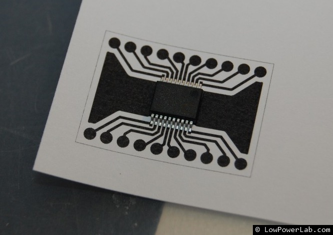
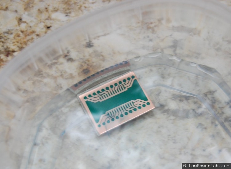
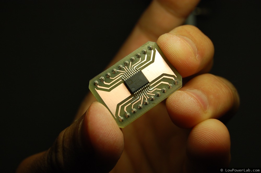
I used to etch PCBs at home, and I still do when I need them fast and it’s easy enough to to etch on 1-layer copper clad. See my post about etching with vinegar!
But PCB making has become so cheap these days that it’s almost not worth bothering. I’ve used more expensive services and cheaper services as well. The more expensive ones tend to be higher quality when you have very fine detail. But for 95% of the cases, even with fine pitch SMD parts (0402 is the smallest I’ve ever used), hobby fabs like OSHPark, or SeedStudio are quite good. The chinese PCBs tend to be OK for most things but the finer SMD footprints you have the lower the quality gets. Continue reading →
I assembled my Moteino circuit inside the KillAWatt. Everything fits very nicely and the LED blinks every ~2 seconds, and data finds its way to my RaspberryPi where EmonCMS records and graphs it nicely. At the last minute I found a leftover TMP36 analog temperature sensor that I had around, and thought – why not add it to the Moteino and report temperature along with power readings?
Here’s the first EagleCAD revision of my Moteino project.
You can find the files on my GitHub repository, along with other projects that I am/will be working on.
I decided to use the MCP1702 3.3v regulator instead of the MCP1700 I started with. There’s no significant difference and allows the Moteino to be powered from a 9V battery (up to ~13V actually)
the onboard LED is not on the traditional D13 line, because that line is used by some SPI devices that pull it up. Consequently the LED would blink (and use some power) whenever talking to SPI devices so I decided to put it on D9 which is a PWM pin. Also it sits on the edge of the board so it’s visible even when you stack something on top
I enlarged the board slightly to allow the RFM12B radio to fit easily underneath when soldering male pins on the bottom. My very first batch was 0.1″ narrower but I had a hard time fitting the radio with male headers next to it. This makes the board slightly wider but easier to use with any kind of headers, above or below
I built my own version of the RFM12B footprint featuring only the necessary (also shorter) pads
The board could be shorter overall at the expense of fewer broken out pins. I decided to keep all the ATMega pins available. The standard Arduino actually does not include A6 and A7!
I’ve been using the RF12 library from Jeelabs for some time for my Moteino testing. This worked just fine and it was a great starting point. However some things were really confusing and I spent a lot of time redoing the same thing over and over again (eg. copy paste from known working code) just because there was a lot of code-overhead to do simple things like sending, receiving, and ACK management, and of course I couldn’t remember any of the functions or macros. Right from start, the need emerged to tweak it into a more flexible and more configurable library, so I kept hacking and modding it until it dawned on me… a new library had to be born. So I decided to completely rewrite it, and wrap the useful functionality in a dedicated C++ class. I modified some of the core features of the Jeelabs version, like adding another header byte to allow 7-bit source and destination addresses (Jeelabs only supports either source or destination in an attempt to save 1 byte), and allow low level configuration of the radio. This yielded a clean and easy to use, yet powerful library (at least it made my life easy). Here’s a summary:
easy API with a few simple functions for basic usage
127 possible nodes on 256 possible networks
66 128 bytes max message length
customizable transmit power (8 levels) for low-power transmission control
customizable air-Kbps rate allows fine tuning the transmission reliability vs speed (transmitting slower is more reliable but takes more time which implies more power usage)
Sleep/Wakeup functionality for power saving
Low battery detector with customizable low voltage threshold
Interrupt driven
Support for targeted ACK instead of broadcasted ACK (possible because of the new source byte in the header)
Support for these chips: ATMega8 family (ATmega168, ATMega328) ATMega2560, ATMega1280, ATMega644P, ATTiny84, ATTiny44, ATMega32u4. So far only tested on ATMega 328/P
The source code and examples are on GitHub:RFM12 Library
I ran some quick tests on the Moteino using a CR1225 coin cell. These cells are tiny, just 12.5mm in diameter, yet they handle the Moteino running low power sketches, or rather, the Moteino can handle running on this tiny cell. Continue reading →
One of my long time interests has been to log my power usage. I have an ongoing project which will enable logging the whole house power consumption. That’s cool but I also wanted a way to log data for individual appliances. So I bought a Tweet-a-Watt starter kit (TAW) from Adafruit. This was a really cool solution to allow me to enhance a Kill-A-Watt power monitor (KAW) and make it transmit the power usage wirelessly so I could graph/log it.
But there was a problem… unfortunately the TAW didn’t work 🙁
After assembling everything, as soon as I would plug in the KAW, the screen would be blank and slowly come to life but still quite unstable and flickery. Data would start coming on the other end but after about 1 minute, the KAW screen would flicker really bad, then go blank and data would stop streaming. I tried a few things but nothing worked. The conclusion was that the XBee radio used by the TAW was drawing too much power and the KAW could not handle its needs. Apparently I had a newer revision KAW which was lower power which could not supply enough power for the TAW. Forums revealed that different revisions of the KAW had similar problems.
So I designed an alternative transmitter circuit using a low power Arduino clone that I designed for other wireless data logging, the Moteino. The operation principle is the same as the circuit from Adafruit. Power comes from the KAW through a Shottky diode to keep dropout low and stop current flow back into the KAW. There’s also a capacitor to help stabilize the circuit when it transmits. The Moteino runs at 3.3v so the current/voltage sampling from the KAW is fed to analog pins on the Moteino through a simple 10kohm<>4.7kohm voltage divider. An LED is used for transmission indication.
A python script was adapted from Adafruit’s version, to read data from a receiver Moteino, graph power and voltage/current waveforms, and also transmit power data to my Emoncms which is running on my RaspberryPi. The results are quite nice, you can see it in action in this video:
This is and introduction to Moteino, a low cost wireless Arduino clone that I designed for my own projects, but since some people started asking about it i decided to try to make it available to others.
Some time ago I started to think of how I could build a simple network of arduino nodes for environmental data harvesting and home automation, but I wasn’t very happy with the existing solutions because they were either not the right size, not battery friendly, I had to hand solder the kits to keep cost low, etc. Ethernet shields are also expensive and running wires around the house was out of the question.
So that’s how the Moteino concept was born. It’s based on the ATMEGA328p and has all the pins exposed, runs at 16Mhz, 3.3v. On the bottom it has a footprint for the RFM12B transceiver which is an excellent alternative to XBee radios, which are at least 3 times more expensive.
UPDATE: I posted some details about a Leonardo version of Moteino (based on ATMega32u4). For more details about MoteinoLeoclick here.
I know there’s many other arduino clones out there that have similar specs. However most of these arduino clones are either somewhat overpriced, they are bulky, or you have to hand-solder them, which if fun for learning how to solder but is time consuming when you just need a bunch of these assembled. If you need 20 or 30 wireless arduino nodes, the time and money you spend can pile up.
So here are the highlights of Moteino:
Low cost Arduino clone fully compatible with the Arduino IDE
Designed for very low power battery operation
The Wireless version includes an onboard RFM12B transceiver and wire antenna
Very small size – 1.3 x0.9 inch
Breadboard friendly header layout allows you to attach female/male header pins on the top or bottom and make shields for it or just use it on the breadboard for prototyping
FTDI programming header
Optiboot bootloader for fast programming and no delay startup
Onboard LED for debugging or visual indication
Standalone version cost is around $10-12 and wireless version about $16, fully assembled
The onboard radio can act as a transmitter or receiver, and I prefer the 434Mhz version because it has longer indoor range and very good wall penetration, but nothing stops you from using a 915Mhz version. Also if you’re in Europe the 434Mhz and 868Mhz bands are legal, not the 915Mhz.
This is my first revision and I still have some minor tweaks I want to make. But i’ll post updates as soon as i have them.
UPDATE: see my other Moteino posts, including Moteino based projects. Example code and RFM12B library at my GitHub repository.
Recently I decided it’s time to dedicate a more professional workspace for all my electronics work where would this go better than the most remote corner of the basement?
Previously I organized my office in one of the home bedrooms but it quickly became obvious that it’s not the best place to keep heat and smoke generating equipment, mix chemicals, etch PCBs, or store parts small parts that get lost in the carpet. Plus I didn’t have outlets where I wanted them and it just didn’t feel right to solder on the office desk.
So I took a break from most of my projects and dedicated almost entirely to planning and building a workspace in my unfinished basement. Long story short, I ended up with a 120sqft room perfect for my needs. I knew I will want to watch my own progress so I captured timelapse videos of the more significant parts of this building project. This happened over several weeks, and if people want details of my planning, building and costs, I can post about that as well. Cheers!
In my first post I’ll describe how I etch PCBs at home with a less conventional but cleaner method, using vinegar as etchant. Yes, vinegar! Vinegar is somewhat slow compared to strong acids like ferric chloride or muriatic (hydrochloric) acid, but its much safer and less hazardous, and there’s an easy way to speed it up. When I first tried it I instantly liked it and never looked back.

 I used to etch PCBs at home, and I still do when I need them fast and it’s easy enough to to etch on 1-layer copper clad. See my post about etching with vinegar!