DoorBell Mote regulator update

The last BellMote prototype ended up having 2 LDO linear regulators, 12V and 3.3V feeding from the 12v one. I was split on using LDOs going forward. The upside is they are cheap, even 2 of them are under $2. The downside is they are inefficient and run warm/hot depending on the load. I could have gone with a single 5V LM7805 which will run even warmer, the higher the gap between Vin and Vout.

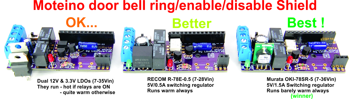
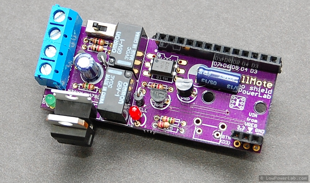
Digikey-ing around, I found these two switching regulators that are drop in SIP replacements for any LM78xx series LDOs: a RECOM 0.5A output with 7-28v input range ($2.8), and a Murata 1.5A 7-36v input range ($4.25). I tried both, and below are the results:

I won’t repeat the captions here but the clear winner is the Murata (plenty stocks at Digikey) it’s quite a bargain given the advantages. I tested it on 24VAC as well and it does not heat up at all either so it will be perfect for some coming interesting projects I have in the works that will feed on 24VAC. The RECOM regulator is just $2.8, still good enough for 16VAC but I prefer the Murata for further 16-24VAC powered projects. That said, I will offer these for sale (2 of them, one RECOM, one Murata, and I will replace the LDOs with a Murata and keep the third one). I may make a kit of this, not sure yet. For now you can grab these two from the first prototype batch, they will be worth millions when LowPowerLab is like Apple and me like Steve Wozniak 30 years from now (-:

Cooling on the cheap: attic fan tests

For some time I wondered if there’s a way to move the cool air in the basement upstairs and make that living space a bit more bearable without running the AC all day long when everyone is gone. As soon as the sun rises and starts hitting the roof in the morning, the attic temps start to blast up towards 150° at the peak around 6pm. The side walls and windows also heat up, act as heat radiators and contribute to warming the interior spaces. Once that attic space and side walls are super heated after a day-long sun blast it’s very hard to cool the interior back down, while heat radiates quickly inside and fights the HVAC’s cooling efforts. The attic 20″ blown insulation does a great job keeping the 2nd level way cooler than the attic, around 87°F, but still feels very toasty, and the decade old HVAC runs almost non stop from 4pm into 11pm to make it bearable enough to go to sleep. All this while the basement temps range from 65-75°F during the day, nice and cool.

Googling around I found some solutions that involve using the HVAC fan to push air from the basement or lowest point in the house all the way upstairs and into the attic (opening the attic hatch). Attics have vents that allow air to flow through and out. So this air movement pushes cool air through the house and into the attic and then outside through those attic vents, thus keeping the attic air from super heating. The outcome is that the HVAC AC will have an easier time to cool down the home in the afternoons, running for less time while the temps bounce less throughout the cooling cycles. Unfortunately running the HVAC fan also requires a vent to be cut into the basement HVAC pipe system so the cooler air can be pulled by the fan and moved up, rather than the air from the return pipes (which brings it from upstairs). I don’t really want to do that, since the HVAC fan is a big heavy 220V inefficient motor.

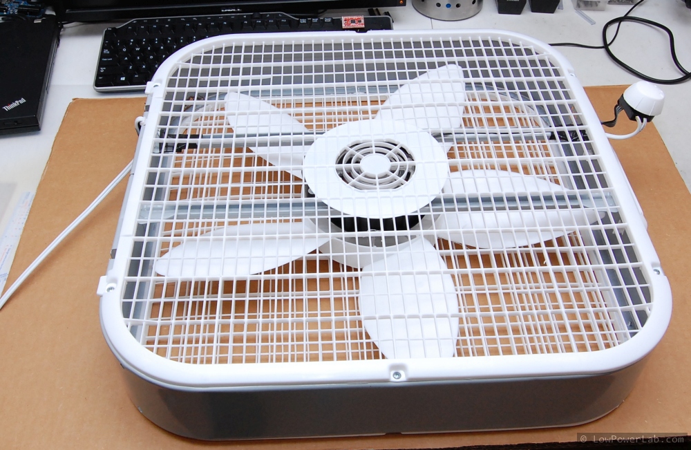
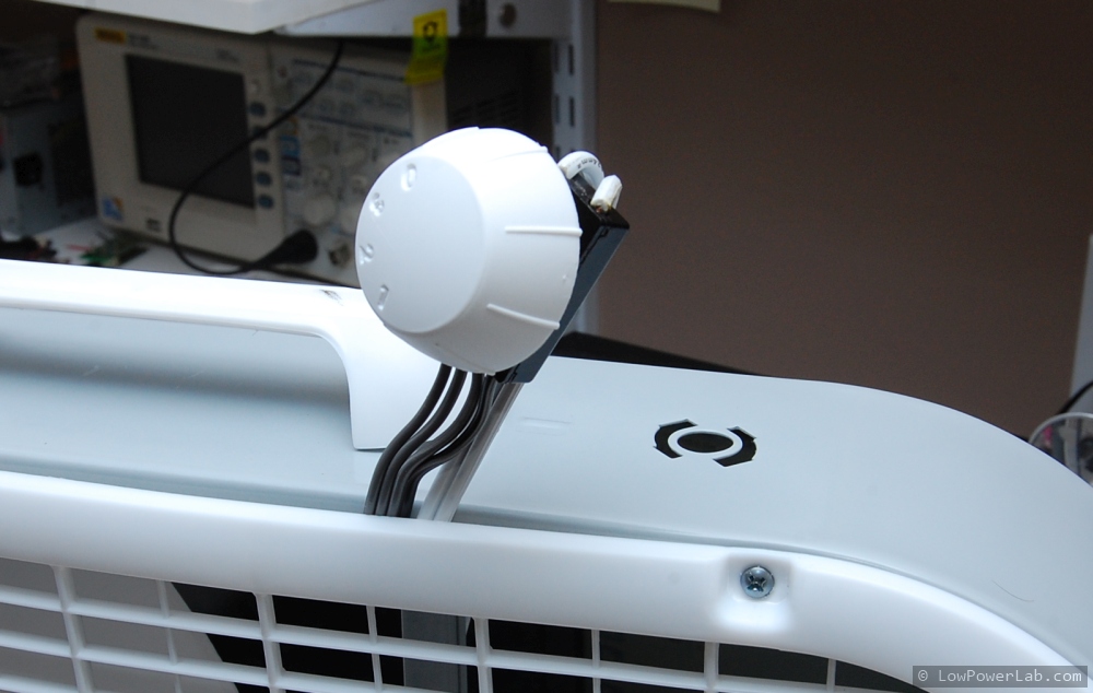
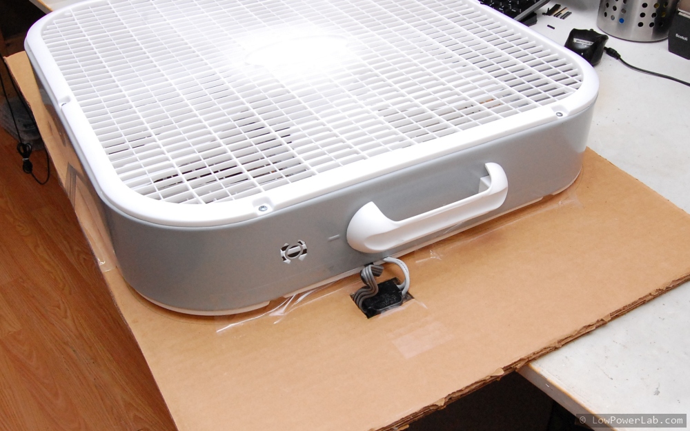
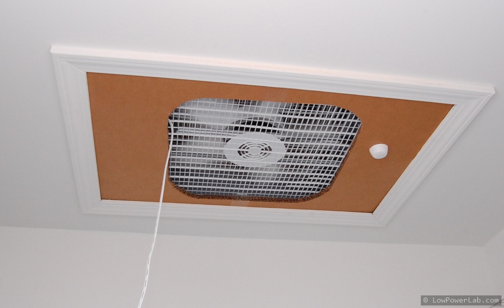
So I’ve just started playing around with some WeatherShields and a cheap Lasko box fan ($17 from HD) that I’ve installed on a thick cardboard cutout which replaces the attic hatch. The fan is good enough for proof of concept and allows easy hacking of the speed knob displacement into the cardboard so I could change speeds from inside the home without climbing on a ladder all the time. For now the power is provided through an extension cable until tests are done, then I plan on making a SwitchMote controlled power outlet in the attic where the fan can plug in, so this could be turned ON/OFF automatically by the Gateway.

Here are a few photos of the fan mod and install. This is just a temporary fitting for some basic tests. A final install would have the fan attached more securely with no air gaps etc.:

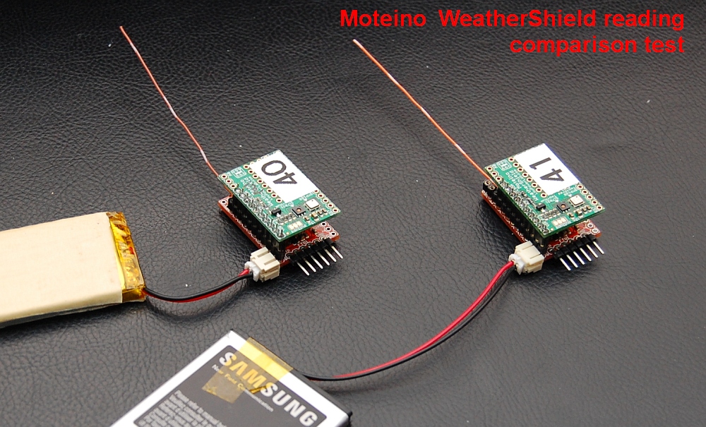
I put together 2 WeatherShields for this test, and added a dedicated Weather node to the gateway. This was a good way to test WeatherShield readings side by side. Results are impressive, I could not see the temp and humidity readings be more than 1% off from each other. BTW I’ve added the new Weather node icon and node definition on the Gateway github repo, and I’ve posted the low power sketch I used on these weather nodes.

Basic fan test data & conclusions

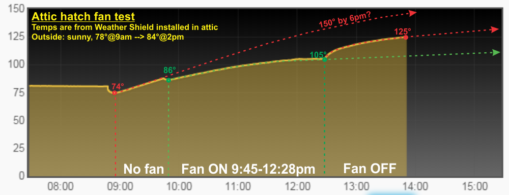
Each level is ~1500sqft, with the attic having a steep slope, so a large air volume. I’ve put one weather sensor node on the second level and the other in the attic. I started measurements around 8:45am when the sun was starting to heat up the attic. One hour later I started the fan and let it run until 12:28pm, almost 4 hours. An open window in the basement (or 1st level) allows air to flow easily and not stress the fan. Here’s a glance of the temperature data from the attic sensor, explanations below:
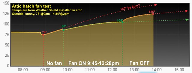
Just looking at it it’s obvious the fan made a big dent. I ran it at max speed which is pretty loud but this is in a closet so that helps contain the fan noise. I’ve seen more expensive similar fans  advertised as very quiet. The point here is to move as much air as possible since the fan would run during the day anyway, when nobody is upstairs to hear the fan noise. I’ve made some projections of what I think would happen if I ran the fan all day or if there was no fan at all.

I will continue to make measurements on comparable days with and without the fan and perhaps update this post, but I think the test is a success. It was a sunny day with 85° tops. If the attic normally heats up to around 140-150° at peak and the 2nd level is around 90° it is very difficult to cool it back down and the AC works very hard. If the fan can reduce the attic temperature by even 20° I assume the AC would not need to work as long and hard to cool the upstairs in the afternoons. I think this simple fan will cost much less to run for 8-10 hours, than running the AC that much harder all afternoon.

A possible improvement to this method is to install more fans in the attic, on top of the vent exhausts to help remove that hot air from the attic, more complex. Or cut a hole in the basement door to add another fan to push air, messy and not wife-friendly. Or stack another fan on the existing one at the attic hatch to increase CFM, just another $17.

To automate and remote control the fan I will need to make a SwitchMote outlet and put it in the attic. That’s for another post.


More Awesome DoorBell Control


UPDATE: I eventually decided to use a single switching regulator that I found on digikey which is both awesome and well priced. See this blog post update about it.

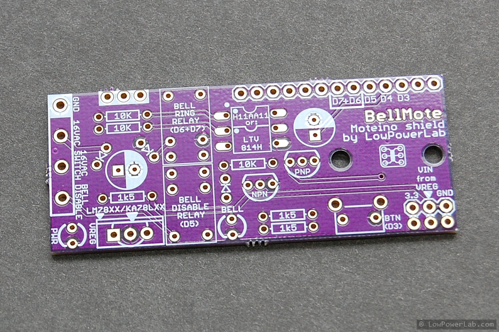
My first DoorBell Mote prototype was working nicely and it allowed monitoring the door bell (while also triggering it remotely – toddlers love it). But I wanted more. On weekends the family likes to get a well deserved nap during the day and often those pesky solicitors ring the bell and wake everyone up. So naturally the doorbell has to be disabled also, without major effort or any disconnected wires. Sounds like the perfect addition to the Door Bell Mote. So I made a new revision and a proper PCB for this, below is the schematic with the changes and the proto PCB from OSHPark. Actually I made more changes to the schematic after putting together the PCB, so there are some differences. I’ve tried a LTV814H optocoupler for AC detection instead of the more expensive H11AA11, it works just as well, but both can be used on this PCB:

bellmote_schematic

There are 2 regulators on this PCB. One is a 12V linear LM7812. The second is a 3.3V linear regulator getting input from the 12V LM output, both in TO220 packages. I know they are super inefficient to convert rectified 16VAC to DC voltages and the critics will stone me for doing this. But here’s the deal – the linears are about 50cents each and I had both among my junk parts. An efficient switching regulator is somewhere between $5-$10. The linears run somewhat warm. The 3.3V regulator only gets warm when I use the disable relay. So they can get warm but not hot, which is fine by me, it’s just a tradeoff. I might make a new revision where I have a single switching regulator such as this one, a drop in replacement for the LM linear regs. Continue reading →

Featured project: Nin10do game console

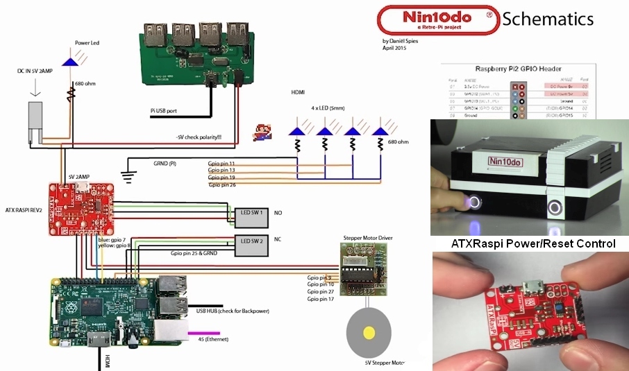
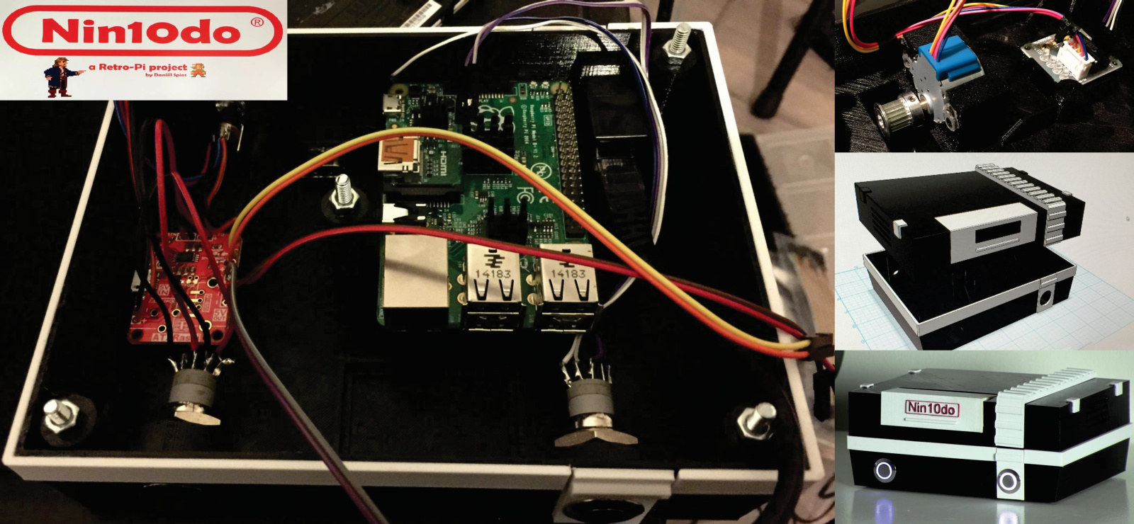
Retro gaming enthusiast Daniel Spies has put together a wonderful RetroPi game console (Now on LifeHacker Australia!) that can emulate popular consoles like NES, MEGADRIVE, PLAYSTATION and has shared his project for posterity. He designed a 3D printed case in Autodesk123D with a stepper motor operated front cover, indicator LEDs, ATXRaspi for power and reset control, and of course the RetroPi for the RaspberryPi OS. It’s one of the most polished projects I’ve seen from an amateur maker/hacker and it includes a series of very detailed youtube walkthroughs of the entire hardware+software setup. Here’s the first part of the video series, where he’s building the wiring/electronics and fitting it into the 3D printed case:

Here are some snapshots I captured that highlight some of the details of the project:

The rest of the videos and more details of the build can be found at his Nin10do Hackaday.io project page. It was a pleasure watching him build this cool project so be sure to check it out as well!

Autonomous filming of GPS+Moteino moving objects

Hackaday.io user [Walker Eric] is an RC airplane enthusiast who wanted to record his plane flights autonomously, without the need of a 3rd hand or having to ask a friend to stand by for this purpose. The flying target should ideally be in the center of the camera field of view. For this purpose he designed a nice video-tracking system composed of a small LiPo powered Moteino+GPS unit that is mounted on the moving target (the RC plane). This reports frequent GPS positioning to the base receiver unit which controls a video camera movement via motors and follows the fast moving RC airplane.

He has managed to produce a really good prototype and has even submitted this as a 2015 Hackaday Prize entry. Zooming is desirable and it’s one of the features he is still working on. Overall this was a great project that Eric has shared with me and I’m quite happy that the Moteinos involved can handle the GPS coordinate transmission between the moving airplane and the base station.

This project could of course be used to autonomously record video of other types of RC moving objects. I can also think of people who want to film themselves doing some activity or record a moving object/animal etc. Check out his project page for more videos, photos and details of the build, and give him a skull!

Moteino Compost Sensor Network with Adafruit-FONA GPRS relay

I occasionally get emails from people that use my products in their projects and some of them are real gems. Other times I just run into them online somewhere or someone tips me off somehow. I did a poor job of keeping track of these but lately I thought I should start presenting the nice ones, maybe there are other people that have interest in similar things.

In this post I’d like to present a compost sensor network built by instructables member kinasmith. Who knew composting can be so interesting and complex.CompostNetwork2

It sounds like composting on a large scale requires careful monitoring of certain parameters so that the pathogens that aid in the process are kept happy and efficient. [Kinasmith] shows off a detailed and beautifully put together instructable that uses Moteinos, temp sensors and a solar powered Moteino+AdafruitFONA gateway to relay the data to his Sparkfun cloud, among other things. He goes into a lot of detail and I really like the nice touches and the effort that went into giving this project more than that hobby level feel. Check this cool project out on instructables.

FEJNV8RI8G5RYIQ.LARGE

Gateway Source Code Released

A few weeks went by since I blogged about the new Gateway interface. I managed to get the code ready and I posted the links on the dedicated gateway page where I prepared a guide to install the stack needed to support it (this will be improved). The code itself and sources are published at Github. There you will find the old interface sample I had posted a long time ago (in the OLD subdirectory, kept there for reference); the files are replaced with the new interface files.

There are 2 directories where you will need to copy files from here after you’ve completed the setup of your Pi from this guide (I may release a Pi image that has everything setup and ready to go). Please note: when you download stuff from Github you must use the Download Zip button in the repository rather than downloading individual files.
First there is the /var/www /default directory, you should copy these files there:

Second there is the /home/pi/moteino directory, you should copy these files there:

Once the gateway starts running it will create the databases for you and start logging data as it comes in from your remote nodes through the gateway Moteino attached to your Pi’s serial port configured in the gateway.js script.

This post is not meant to replace the guide found at the lowpowerlab.com/gateway page. I will post further details there. I created a new forum for discussing this and other gateway related topics so please post your questions there.

Gateway Dashboard Overview

I’ve been talking about a new gateway interface for a while in the forum. I will release more details and the source code soon. Here’s an overview that I’ve put together the past week,  and some screenshots below with graphs and other available features:

Here are some more screenshots:

MAILBOX_DSC_7214DOORBELL_DSC_7220
MOTION_DETAILSMOTION
SWITCHMOTE_DETAILSWITCHMOTE_GRAPH
GARAGE_DETAILGARAGE_GRAPH
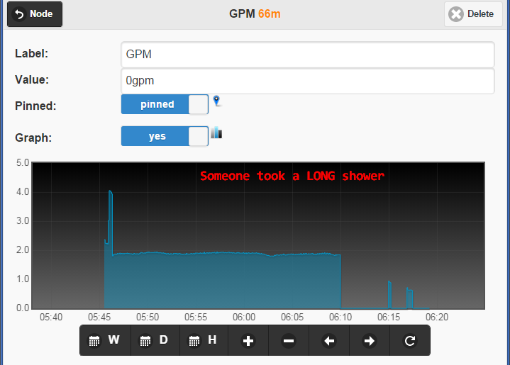
DOORBELL_DETAILSDOORBELL_GRAPH
WATER_GRAPHSUMP_Graph2

This content will be updated and improved on the dedicated Moteino Gateway page where all the source code and details will be published.

DoorBell + Moteino = Awesome

UPDATE: Check out the new version of this, now with bell enable/disable function!

A lonely doorbell activated by a boring push-button at the front door is not very exciting in a world of Arduino and “Internet of Things”. I’ve been wanting to Arduinize the doorbell into the Moteino Framework gateway interface so that I could:

  • observe/count/graph when the doorbell is used
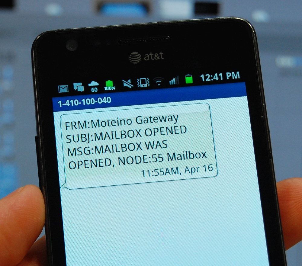
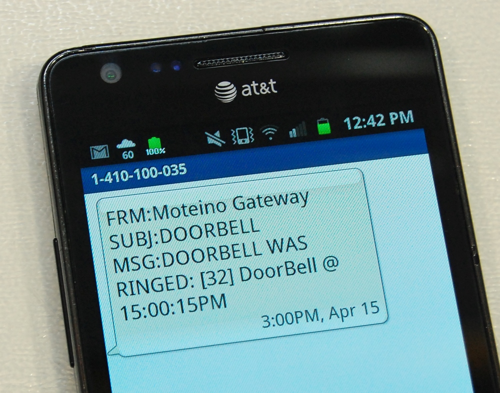
  • get notified when someone rings it if I am not at home (email, SMS etc)
  • play a sound when I am in my lab where I have a hard time hearing the chime (did I hear it or not? should I go upstairs to check? nah… I’m too busy for that)
  • ring the bell if I want to, *remotely* from your mobile device (why not right? just detecting is too boring)

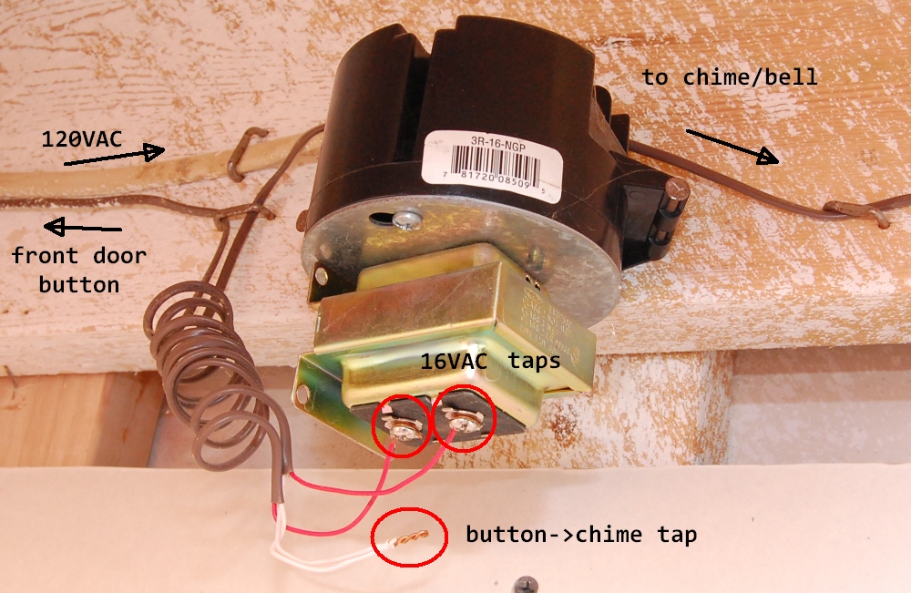
Below is a schematic of what a typical wired door bell circuit looks like, and also a photo of what it looks like in my house. The dotted green rectangle is the circuit that I have physical access to – pictured next to it in my basement (and I don’t have a back door button):

I have a single button (front door) and probably most houses do. So I only care to inject my solution for that front door button. There is typically a 16VAC transformer powered from mains that activates the chime when the switch is pressed. So there are a few issues to solve in order to tap into this circuit, detect button presses and also being able to control it via Moteino:

  • Power our circuit from the 16VAC doorbell transformer. This is a good exercise to  create a DC power source from an AC source. We’ll use a simple half wave rectifier to achieve this
  • Detect when this 16VAC current flows through the wire coming from the outside button. When the button is pressed, the chime will ring and our circuit detects the AC current and outputs a digital HIGH for the Moteino input pin that monitors it
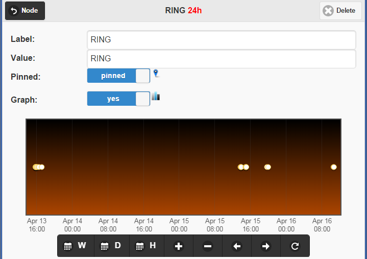
  • Make the Moteino “press” the door bell button when it receives a “RING” wireless message

I will explain these points step by step. Let’s get to work! Continue reading →

Sump pump fails: SonarMote intercepts!

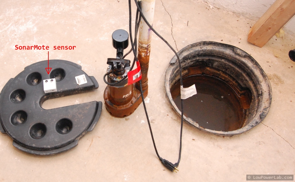
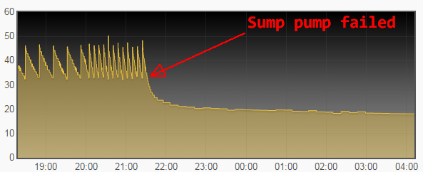
Yesterday the first significant storm of the season moved in the area and it rained heavily into the evening hours. Nice for the grass, I just fertilized it the other day. But bad for sump pumps which work really hard to keep the water out of the house, they usually fail during a big storm. I came back home very late and was very tired, went straight to bed so I didn’t notice anything. This morning when I checked the Moteino Gateway interface (coming soon!), I was alerted that the sump pump SonarMote was reading an unusually low value. The SonarMote sensor that sends the readings was still operational since the data was still coming. So could the sump pump have failed? Here’s the graph that recorded the increasing frequency of the pump operation until the failure ocurred (lower value means water is closer to the sensor and hence fuller well tank):

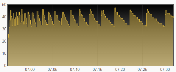
So I head down to the basement to check and sure enough, the sump well was full of water and the sump pump did not work. So I remove the pump to inspect it and as I was getting ready to head to Home Depot before the new pumps are all gone, I fiddle with it and it turns out the plunger was stuck in a low position so it was not actuating the pump. I could get it mobile again and it seems that fixed it, but it might fail again if there’s debris/sand inside the plunger cylinder, so I will keep an eye on this. Anyway after putting it back in the well here’s the pattern picked up by the SonarMote. Very frequent starts as the stagnant water in the perimeter drains into the sump well and the pump works hard to get the water out as it refills the tank:

Without being aware what’s going on, eventually the water would have overflown into the basement. Sure glad I have that sensor to alert me in time.