WeatherShield is a versatile board that hosts the highly accurate BME280 THP sensor (temperature, humidity, atmospheric pressure).
The BME280 sensor was chosen for revision R2 of the WeatherShield because it’s a great sensor that includes all 3 major atmospheric readings we are most interested in. The previous SMD footprint for the Si7021 sensor (used in R1) is left unpopulated and could in fact be used of desired.
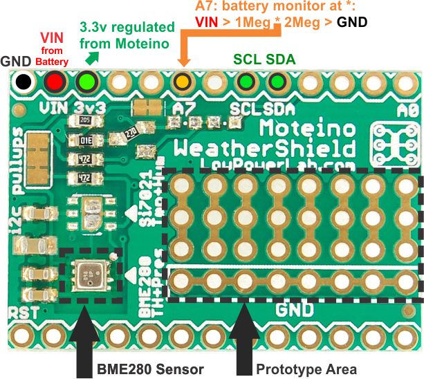
While the layout of the board is designed to stack with a Moteino, there are only a few required pins to use the WeatherShield. In fact you could get by with only 4 pins if you wanted to use the board with another type of arduino: GND, 3.3v, SCL and SDA.
Note that the BME280 sensor will require 1.71-3.6V (supplied via the 3v3 pin), anything more will damage the sensor!
The BME280 sensor is wired to use the default I2C interface with the default 0x77 address.
Battery/VIN monitor
The VIN pin is used in a voltage divider that is then fed to A7 on the Moteino, which can then read this value and estimate the battery or VIN voltage.
This divider has a ratio of 2/3 of the actual VIN and is required because the VIN is greater than the 3.3V operating voltage of the Moteino. This means a readable VIN range through this monitor is up to about 5V before A7 saturates to the max reading of 1023 (10bit ADC on the ATMega328p), hence the recommended voltage on VIN should be around 5V.
Disabling the VIN monitor
The monitor is permanently wired to VIN and at 5V will drain about 1.6uA. This is a very small amount of current and the previous revision included a mosfet to disable the monitor when not in use, in fact the pads are still there to support it but a jumper was placed instead to permanently enable it (the angled resistor). If you do not want to use this monitor and need to save that extra tiny amount of current you can do so by cutting the trace below, or if you’re brave enough, you may desolder the angled resistor and solder a SOT23-3 P-mosfet which has its gate wired to A3.
I2C interface
Note that SCL and SDA are pulled up with 4.7K resistors. The left side of the board has SMD jumpers which you can break to disable these resistors or use different values, but the default values should always work. If you have other I2C
Also check out this extensive comparison between BME280 and many other temperature/humidity sensors, the conclusion being that the BME280 is the clear winner among the tested devices.
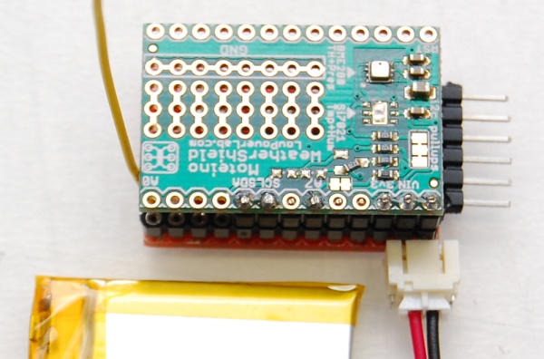
Here’s a very simple setup that includes a Moteino with RFM69CW radio and WeatherShield (R2). This setup uses a small LiPo 500mAh battery as power source. A JST connector can be soldered directly to the Moteino GND-VIN pins to accept the typical LiPo battery with a mating connector.
Notice that only the few required header pins need to be soldered for connecting to the Moteino, the others can be left unpopulated.
The Moteino will need at least 3.5V to run above the dropout voltage of the onboard MCP1703 LDO regulator. Whether you use a LiPo battery or any other VIN source (ex. 3xAAA) you should always make sure the polarity is correct to avoid damage to the boards.
Let’s try a simple sketch that will just read the sensor data and voltage monitor and display this to the serial monitor. Make sure you have installed the Sparkfun BME280 library that is required.
//******************************************************************************
//This code is released under the [MIT License](http://opensource.org/licenses/MIT).
//Please review the LICENSE.md file included with this example. If you have any questions
//or concerns with licensing, please contact techsupport@sparkfun.com.
//Distributed as-is; no warranty is given.
//******************************************************************************
#include  //Get it here: https://github.com/sparkfun/SparkFun_BME280_Arduino_Library
#include
#include
//******************************************************************************
#define BATT_MONITOR  A7
#define BATT_FORMULA(reading) reading * 0.00322 * 1.53 //fine tune this to match your Batt Voltage when fully charged
#define SERIAL_BAUD   115200
BME280 bme280;
//******************************************************************************

void setup()
{
  Serial.begin(SERIAL_BAUD);
  Serial.print("Program Started\n");
  Serial.print("Starting BME280... result of .begin(): 0x");

  delay(10);  //BME280 requires 2ms to start up.

  bme280.settings.commInterface = I2C_MODE;
  bme280.settings.I2CAddress = 0x77;
  bme280.settings.runMode = 3; //Normal mode
  bme280.settings.tStandby = 0;
  bme280.settings.filter = 0;
  bme280.settings.tempOverSample = 1;
  bme280.settings.pressOverSample = 1;
  bme280.settings.humidOverSample = 1;
  bme280.begin();

  Serial.print("Chip ID(0xD0): 0x");
  Serial.println(bme280.readRegister(BME280_CHIP_ID_REG), HEX);
  Serial.println();
}

char Pstr[10];
char Fstr[10];
char Hstr[10];
char buffer[100];
float batteryVolts = 5;
char BATstr[10];

void loop()
{
  batteryRead();

  bme280.begin();
  dtostrf(bme280.readTempF(), 3,2, Fstr);
  dtostrf(bme280.readFloatHumidity(), 3,2, Hstr);
  dtostrf((bme280.readFloatPressure()/100)*0.0295333727, 3,2, Pstr);
  sprintf(buffer, "Temperature_F:%s  Humidity_%%:%s  Pressure_inHg:%s VIN:%s", Fstr, Hstr, Pstr, BATstr);
  Serial.println(buffer);
  bme280.writeRegister(BME280_CTRL_MEAS_REG, 0x00); //sleep the BME280
  delay(2000);
}

void batteryRead()
{
  unsigned int readings=0;
  for (byte i=0; i<10; i++) //take 10 samples, and average
    readings+=analogRead(BATT_MONITOR);
  batteryVolts = BATT_FORMULA(readings / 10.0);
  dtostrf(batteryVolts, 3,2, BATstr);
}
Load this to your Moteino and you should then see output like this in your serial monitor:
Now let’s try to send this to another Moteino wirelessly. Load this sketch instead, and adjust the settings to match your transceiver hardware. If you have an IoT Gateway setup you will see the new Weather Sensor node pop up in the dashboard as soon as power is applied. Click on that new node, configure it as Weather Sensor, then it will look like this:
In the details, you should see all the details, including the voltage:
After some time collecting data you can start seeing patterns, here’s a day worth of temperature readings:
If you just have another receiving Moteino with RFM69 transceiver on the other end (use this sketch and make sure radio settings match!), you will simply see the message in that receiver’s serial monitor.
You may also find this 3rd party video useful where John shows his WeatherShield + Moteino assembly and setup and data visualization:
John from John’s DIY Playground put together a nice video of setting up a Weather Node powered by a PowerShield from a LiPo battery, watch his assembly and demo below: