Prepare the MightyBoost and Moteino for mating, solder the headers and program the Moteino with the MightyBoost sketch using an FTDI-Adapter or equivalent USB-serial adapter. This combo will provide:
- battery backup (in case power goes out)
- battery charging while MightyBoost USB is plugged in – ensure you have a good 2A+ USB power supply – when plugged in this powers the Pi+display and also charges the battery!
- Pi 5V boosted power from a LiPo battery
- convenient reboots and shutdowns from the push of a button

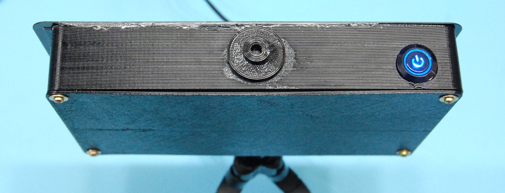
You will need a momentary push button (non latching switch), such as this one which also has the integrated status LED, and I recommend either soldering wires for power, or use high quality jumper wires such as these to ensure the voltage doesn’t dip to your Pi and then to the display.
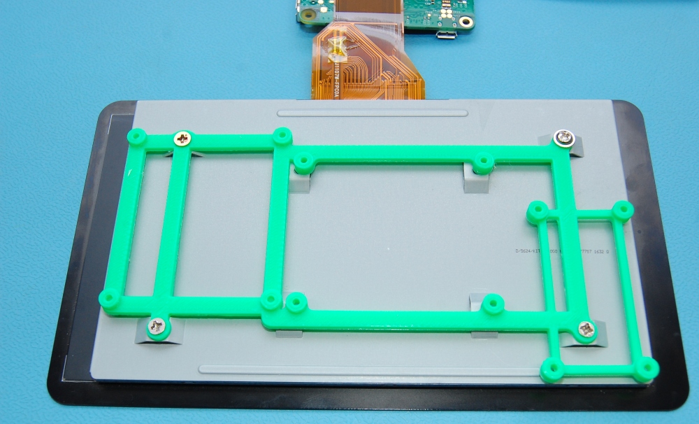
Proceed to mounting the display board, RaspberryPi and the MightyBoost+Moteino to the frame using short M2.5 screws or similar. Add a LiPo battery and power the MightyBoost to ensure the battery is charging (red LED on if not already charged) and 5V power is ready (green LED on when battery or USB power is provided).
The wiring can be seen in the photo below, you can also see the MightyBoost guide for specific details of its own wiring and principle of operation.
The wiring summary is as follows:
- Main power comes in through the MightyBoost USB port which keeps the battery charged. It falls back on battery boost when USB power is disconnected, powers the Pi+display as long as there is juice in the battery
- The Moteino controls the MightyBoost and a momentary (non-latching) button is required. In addition, an output power status LED indicator is available to show when 5V* output power is ON. These 4 button connections are seen below in yellow, and blue/green for the button’s internal LED
- The 5V* output from the MightyBoost is controlled by this button, and is wired to the Pi GPIO pins 2 & 6 (5V, GND)
- The BootOK/Shutdown signals from the MightyBoost are connected to the Pi’s pins 24 and 26 respectively (ie. GPIO8 and GPIO7), these are picked up by the shutdown.sh script we will install in the next section
- Finally, connect the display ribbon cable to the Pi, and the Display control board also needs 5V power, take it from the Pi’s extra 5V and GND pins 4 and 9 (or better: solder it directly to the MightyBoost’s 5V* output)

You can test power the setup and the Pi should boot and screen should be active. The screen shares its power with the Pi’s 5V power rail. You should see at least 5V on the display 5V pin, if not, your connections might not be good enough and the screen might become unstable, check your wiring again.