M0 Sensor Shields
There are now a few compact low-power sensor breakouts available that can flat-mount straight on the M0 PCB (bottom side).
BME280 Breakout
This breakout includes a BME280 sensor (same sensor as the popular WeatherShield):

Please see the WeatherShield guide for sample code.
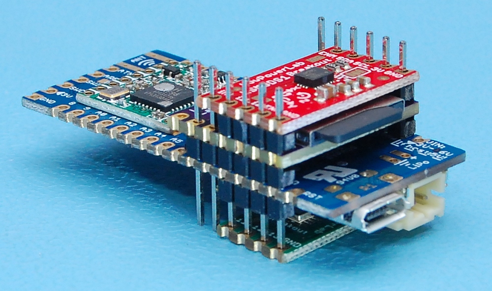
LSM9DS1 9DoF IMU Breakout
There is now a 9D0F LSM9DS1 sensor breakout which includes 3 sensors in 1 chip – 3-axis accelerometer, 3-axis gyroscope and 3-axis magnetometer!

Here’s a sample sketch that you can use to get the various readings available from the LSM9DS1 sensors:
/*****************************************************************
SFE_LSM9DS1 Library Simple Example Code - I2C Interface
The LSM9DS1 is a versatile 9DOF sensor. It has a built-in
accelerometer, gyroscope, and magnetometer. Very cool!

This Arduino sketch is a demo of the simple side of the SFE_LSM9DS1 library.
It'll demo the following:
* How to create a LSM9DS1 object, using a constructor (global variables section).
* How to use the begin() function of the LSM9DS1 class.
* How to read the gyroscope, accelerometer, and magnetometer
  using the readGryo(), readAccel(), readMag() functions and
  the gx, gy, gz, ax, ay, az, mx, my, and mz variables.
* How to calculate actual acceleration, rotation speed,
  magnetic field strength using the calcAccel(), calcGyro()
  and calcMag() functions.
* How to use the data from the LSM9DS1 to calculate
  orientation and heading.

This example demonstrates how to use I2C. The pin-out is as follows:
   LSM9DS1 --------- Moteino
	 SCL ------------- SCL (A5 on Moteino/Arduino)
	 SDA ------------- SDA (A4 on Moteino/Arduino)
	 VDD ------------- 3.3V
	 GND ------------- GND

The LSM9DS1 has a maximum voltage of 3.6V. Make sure you power it
off the 3.3V rail! I2C pins are open-drain, so you'll be
(mostly) safe connecting the LSM9DS1's SCL and SDA pins
directly to a Moteino/Arduino.

Code by Jim Lindblom @ SparkFun Electronics
Adapted for MoteinoM0 by Felix Rusu, LowPowerLab.com
Original Creation Date: April 30, 2015
Distributed as-is; no warranty is given.
*****************************************************************/
// The SFE_LSM9DS1 library requires both Wire and SPI be
// included BEFORE including the 9DS1 library.
#include <Wire.h>
#include <SPI.h>
#include <SparkFunLSM9DS1.h>

#ifdef MOTEINO_ZERO
  #ifdef SERIAL_PORT_USBVIRTUAL
    #define Serial SERIAL_PORT_USBVIRTUAL // Required for Serial on Zero based boards
  #endif
#endif

//////////////////////////
// LSM9DS1 Library Init //
//////////////////////////
// Use the LSM9DS1 class to create an object
LSM9DS1 imu;

///////////////////////
// Example I2C Setup //
///////////////////////
// SDO_XM and SDO_G are both pulled high, so our addresses are:
#define LSM9DS1_M	0x1E // Would be 0x1C if SDO_M is LOW
#define LSM9DS1_AG	0x6B // Would be 0x6A if SDO_AG is LOW

////////////////////////////
// Sketch Output Settings //
////////////////////////////
#define PRINT_CALCULATED
//#define PRINT_RAW
#define PRINT_SPEED 1000 // 250 ms between prints

// Earth's magnetic field varies by location. Add or subtract
// a declination to get a more accurate heading. Calculate
// your's here:
// http://www.ngdc.noaa.gov/geomag-web/#declination
#define DECLINATION -8.58 // Declination (degrees) in Boulder, CO.

#ifdef MOTEINO_ZERO
  #ifdef SERIAL_PORT_USBVIRTUAL
    #define Serial SERIAL_PORT_USBVIRTUAL // Required for Serial on Zero based boards
  #endif
#endif

void setup()
{
  pinMode(LED_BUILTIN,OUTPUT);
  Serial.begin(115200);
  Wire.begin();
  delay(2000);
}

byte imuSetup() {
  // Before initializing the IMU, there are a few settings
  // we may need to adjust. Use the settings struct to set
  // the device's communication mode and addresses:
  imu.settings.device.commInterface = IMU_MODE_I2C;
  imu.settings.device.mAddress = LSM9DS1_M;
  imu.settings.device.agAddress = LSM9DS1_AG;
  // The above lines will only take effect AFTER calling
  // imu.begin(), which verifies communication with the IMU
  // and turns it on.
  if (!imu.begin())
  {
    Serial.println("Failed to communicate with LSM9DS1.");
    Serial.println("Double-check wiring.");
    Serial.println("Default settings in this sketch will " \
                  "work for an out of the box LSM9DS1 " \
                  "Breakout, but may need to be modified " \
                  "if the board jumpers are.");
    return false;
  }
  return true;
}

void loop()
{
  if (imuSetup()) {
    printGyro();  // Print "G: gx, gy, gz"
    printAccel(); // Print "A: ax, ay, az"
    printMag();   // Print "M: mx, my, mz"

    // Print the heading and orientation for fun!
    // Call print attitude. The LSM9DS1's magnetometer x and y axes are opposite to the accelerometer, so my and mx are substituted for each other.
    printAttitude(imu.ax, imu.ay, imu.az, -imu.my, -imu.mx, imu.mz);
    Serial.println();
  }
  delay(PRINT_SPEED);
  //imu.sleepGyro();
}

void printGyro()
{
  // To read from the gyroscope, you must first call the
  // readGyro() function. When this exits, it'll update the
  // gx, gy, and gz variables with the most current data.
  imu.readGyro();

  // Now we can use the gx, gy, and gz variables as we please.
  // Either print them as raw ADC values, or calculated in DPS.
  Serial.print("G: ");
#ifdef PRINT_CALCULATED
  // If you want to print calculated values, you can use the
  // calcGyro helper function to convert a raw ADC value to
  // DPS. Give the function the value that you want to convert.
  Serial.print(imu.calcGyro(imu.gx), 2);
  Serial.print(", ");
  Serial.print(imu.calcGyro(imu.gy), 2);
  Serial.print(", ");
  Serial.print(imu.calcGyro(imu.gz), 2);
  Serial.println(" deg/s");
#elif defined PRINT_RAW
  Serial.print(imu.gx);
  Serial.print(", ");
  Serial.print(imu.gy);
  Serial.print(", ");
  Serial.println(imu.gz);
#endif
}

void printAccel()
{
  // To read from the accelerometer, you must first call the
  // readAccel() function. When this exits, it'll update the
  // ax, ay, and az variables with the most current data.
  imu.readAccel();

  // Now we can use the ax, ay, and az variables as we please.
  // Either print them as raw ADC values, or calculated in g's.
  Serial.print("A: ");
#ifdef PRINT_CALCULATED
  // If you want to print calculated values, you can use the
  // calcAccel helper function to convert a raw ADC value to
  // g's. Give the function the value that you want to convert.
  Serial.print(imu.calcAccel(imu.ax), 2);
  Serial.print(", ");
  Serial.print(imu.calcAccel(imu.ay), 2);
  Serial.print(", ");
  Serial.print(imu.calcAccel(imu.az), 2);
  Serial.println(" g");
#elif defined PRINT_RAW
  Serial.print(imu.ax);
  Serial.print(", ");
  Serial.print(imu.ay);
  Serial.print(", ");
  Serial.println(imu.az);
#endif
}

void printMag()
{
  // To read from the magnetometer, you must first call the
  // readMag() function. When this exits, it'll update the
  // mx, my, and mz variables with the most current data.
  imu.readMag();

  // Now we can use the mx, my, and mz variables as we please.
  // Either print them as raw ADC values, or calculated in Gauss.
  Serial.print("M: ");
#ifdef PRINT_CALCULATED
  // If you want to print calculated values, you can use the
  // calcMag helper function to convert a raw ADC value to
  // Gauss. Give the function the value that you want to convert.
  Serial.print(imu.calcMag(imu.mx), 2);
  Serial.print(", ");
  Serial.print(imu.calcMag(imu.my), 2);
  Serial.print(", ");
  Serial.print(imu.calcMag(imu.mz), 2);
  Serial.println(" gauss");
#elif defined PRINT_RAW
  Serial.print(imu.mx);
  Serial.print(", ");
  Serial.print(imu.my);
  Serial.print(", ");
  Serial.println(imu.mz);
#endif
}

// Calculate pitch, roll, and heading.
// Pitch/roll calculations take from this app note:
// http://cache.freescale.com/files/sensors/doc/app_note/AN3461.pdf?fpsp=1
// Heading calculations taken from this app note:
// http://www51.honeywell.com/aero/common/documents/myaerospacecatalog-documents/Defense_Brochures-documents/Magnetic__Literature_Application_notes-documents/AN203_Compass_Heading_Using_Magnetometers.pdf
void printAttitude(
float ax, float ay, float az, float mx, float my, float mz)
{
  float roll = atan2(ay, az);
  float pitch = atan2(-ax, sqrt(ay * ay + az * az));

  float heading;
  if (my == 0)
    heading = (mx < 0) ? 180.0 : 0;
  else
    heading = atan2(mx, my);

  heading -= DECLINATION * PI / 180;

  if (heading > PI) heading -= (2 * PI);
  else if (heading < -PI) heading += (2 * PI);
  else if (heading < 0) heading += 2 * PI;

  // Convert everything from radians to degrees:
  heading *= 180.0 / PI;
  pitch *= 180.0 / PI;
  roll  *= 180.0 / PI;

  Serial.print("Pitch, Roll: ");
  Serial.print(pitch, 2);
  Serial.print(", ");
  Serial.println(roll, 2);
  Serial.print("Heading: "); Serial.println(heading, 2);
}
SD-card Logger Breakout
Need a few gigs of logging memory to complement your MoteinoM0 or other wireless projects? It's no problem with this mini SD-card breakout which includes a power switch to put your SD-Card to sleep.

Here's a simple sketch for MoteinoM0 that will read the SD-Card content then sleep the SD card and everything else (radio, FLASH-MEM, if any) for sub 10uA sleep:
/*****************************************************************
 LowPowerLab SD-card Breakout Listfiles Example Sketch
 This example shows how to list the files on an SD card
 For MoteinoM0 this can be flat-mounted on the PCB, just align with SPI pins
 Wiring for use with other Moteinos/Arduinos using SPI bus:
  MOSI - pin 11
  MISO - pin 12
  CLK - pin 13
  CS - pin 4
*****************************************************************/
#include <SPI.h>
#include <SD.h>
#include <SPIFlash.h>         //get it here: https://www.github.com/lowpowerlab/spiflash
#include <RFM69.h>    //get it here: https://www.github.com/lowpowerlab/rfm69
/****************************************************************/
#define NODEID        2   //must be unique for each node on same network (range up to 254, 255 is used for broadcast)
#define NETWORKID     100  //the same on all nodes that talk to each other (range up to 255)
#define GATEWAYID     1
#define FREQUENCY     RF69_915MHZ
#define IS_RFM69HW_HCW //uncomment only for RFM69HW! Leave out if you have RFM69W!
/****************************************************************/
#ifdef MOTEINO_M0
  #define SD_CS    10
  #define SD_ON    11
#endif

#define BOARD_MOSI_PORT  (1)
#define BOARD_MOSI_PIN   (10)
#define BOARD_MISO_PORT  (0)
#define BOARD_MISO_PIN   (12)
#define BOARD_SCK_PORT   (1)
#define BOARD_SCK_PIN    (11)
//#define SS_PORT        (1)
//#define SS_PIN         (9)
#define SD_CS_PORT       (0)
#define SD_CS_PIN        (18)

RFM69 radio;  //#if defined (__AVR_ATmega32U4__) RFM69 radio(8,7);
SPIFlash flash(SS_FLASHMEM, 0xEF30); //EF30 for 4mbit  Windbond chip (W25X40CL)
File root;

void setup() {
  pinMode(LED_BUILTIN, OUTPUT);
  pinMode(SS_FLASHMEM, OUTPUT);
  pinMode(A2, OUTPUT);
  pinMode(SD_CS, OUTPUT);
  pinMode(SD_ON, OUTPUT);
  digitalWrite(SS_FLASHMEM, HIGH);
  digitalWrite(A2, HIGH);
  digitalWrite(SD_CS, HIGH);
  digitalWrite(SD_ON, HIGH);

  Serial.begin(115200);
  delay(5000);

  if (radio.initialize(FREQUENCY,NODEID,NETWORKID))
  {
    Serial.println("Radio init OK, putting it to sleep...");
    radio.sleep();
  }
  else {
    Serial.println("Radio init fail, moving on...");
    //return;
  }

  if (flash.initialize())
  {
    Serial.println("Flash-MEM init OK, putting it to sleep...");
    flash.sleep();
  }
  else {
    Serial.println("Flash init fail, moving on...");
    //return;
  }

  digitalWrite(SD_ON, LOW); //SD power ON

  if (SD.begin(SD_CS))
  {
    Serial.println("SD card init OK, listing content...");
    root = SD.open("/");
    printDirectory(root, 0);
    Serial.println("done!");
  }
  else {
    Serial.println("SD card init fail, moving on");
    //return;
  }

  digitalWrite(LED_BUILTIN, HIGH);
  Serial.println("Sleeping MCU in 3 seconds...");
  delay(3000);

  digitalWrite(LED_BUILTIN, LOW);
  digitalWrite(SD_ON, HIGH); //SD power OFF

  //reset SD CS direction to ensure there is no drainage
  PORT->Group[SD_CS_PORT].OUTCLR.reg = (1<<SD_CS_PIN);
  PORT->Group[SD_CS_PORT].DIRCLR.reg = (1<<SD_CS_PIN);
  PORT->Group[BOARD_MOSI_PORT].PINCFG[BOARD_MOSI_PIN].reg = 0;

  Serial.flush();
  delay(5000);

  standbySleep(); //puts the M0 to "forever" deep sleep for lowest power sleep mode
}

void loop() {
  //nothing here
}

void printDirectory(File dir, int numTabs) {
  while (true) {

    File entry =  dir.openNextFile();
    if (! entry) {
      // no more files
      break;
    }
    for (uint8_t i = 0; i < numTabs; i++) {
      Serial.print('\t');
    }
    Serial.print(entry.name());
    if (entry.isDirectory()) {
      Serial.println("/");
      printDirectory(entry, numTabs + 1);
    } else {
      // files have sizes, directories do not
      Serial.print("\t\t");
      Serial.println(entry.size(), DEC);
    }
    entry.close();
  }
}

void standbySleep() {
    // Set sleep mode
  SCB->SCR |= SCB_SCR_SLEEPDEEP_Msk;

  //Disable USB
  USB->DEVICE.CTRLA.reg &= ~USB_CTRLA_ENABLE;

  //Enter sleep mode
  __WFI();

  //...Sleep forever

  //Enable USB
  USB->DEVICE.CTRLA.reg |= USB_CTRLA_ENABLE;
}
As can be seen in the commented code, here are the required connections for this breakout (also marked on the silkscreen):
- SPI pins (MI, MO, SCK, CS)
- power (3V, GND)
- EN (power enable) - this needs to go LOW as in the sample code to provide power to the SD card
- CD (card detect) - this one has an OPEN solder jumper, this pin is not commonly used
Nothing stops you to mount all three of the above breakouts on a single Moteino M0, just be careful to align the pins correctly!