
Assembly
Start by preparing the parts needed. Cut the 40 pin female header into 4 parts: 2×13 (needed), 1×8 (optional if you don’t use the screw terminal), 1×3 (optional if you power via jack). As you cut each section, you will loose a position, and 40 pins won’t allow for slack so be careful. For instance, to cut the first two 13 pin female headers you always need to cut on the 14th position (which will be lost), as illustrated in the photos. You can use the shield to insert the header in the 13 pin holes and cut on the 14th position. Trim the excess plastic casing on the edges and you are left with the 4 pieces needed:
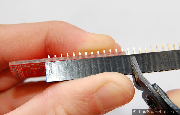 | 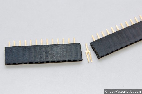 |  | 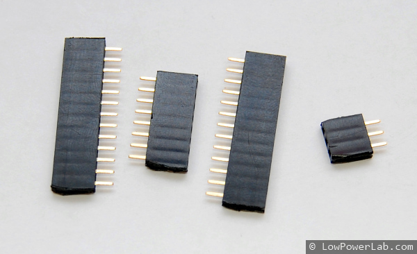 |
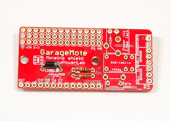
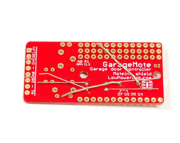
Now start soldering the small/low profile parts, resistors & diode. Mind the diode orientation, match the silver band to the white band on the silkscreen. Then add the headers, button, jack, relay. Now’s a good time to cut 2×13 male headers (from the provided 1×40 male header) for the Moteino (sold separately), then you can mate the male+female headers and use the Moteino to keep them straight and solder all joints on the GarageMote PCB and also on the Moteino. When finished, trim all the excess leads with a flush cutter to allow sticking the velcro:
 |  |  | 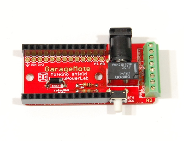 | 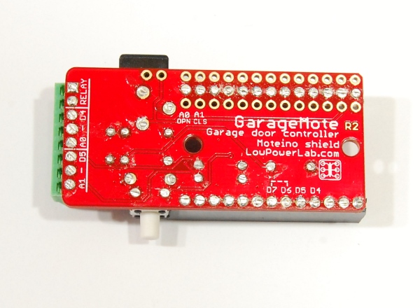 | 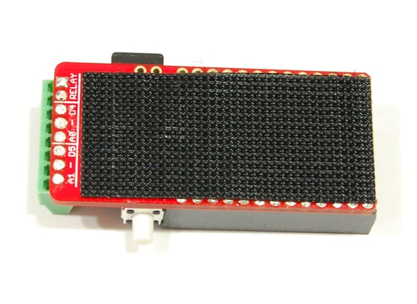 |
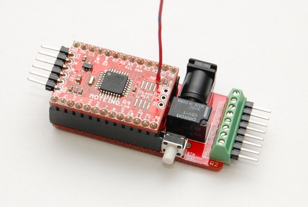
When this is all done, your GarageMote should look like this. Note I added a 1×8 male header in the screw terminal since I
 |  |
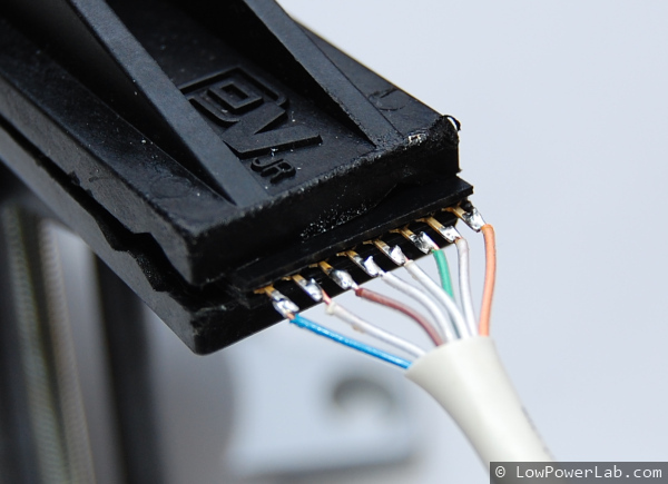
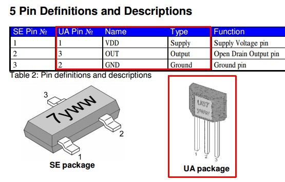
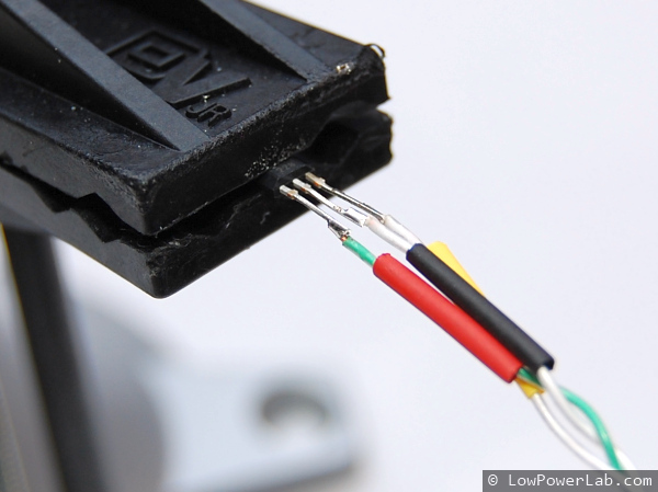
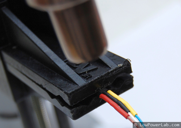
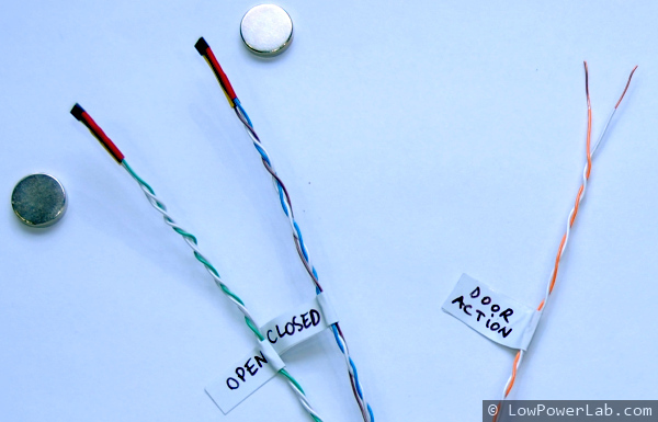
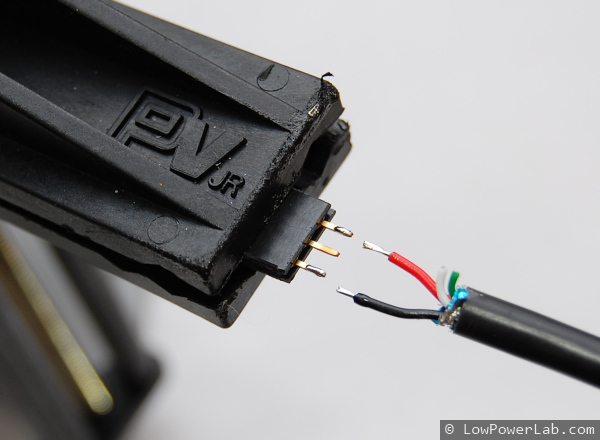
Proceed to prepare the 8-wire CAT5 cable. Remove about 70% of the cable wrapping. Since there is a screw terminal, you should probably just screw one end of the cable directly. I already had an older cable with headers already soldered, so I screwed in the male header instead. Use the wire colors to your advantage, make notes if necessary to make sure you match the pins for the sensors correctly. Note that the orientation of the sensor is important with respect to magnetic field orientation. GarageMote R2 now comes with unipolar sensors that will detect a magnet regardless of the magnet pole. See the pinout photo for details – each sensor has a GND, a VCC and an OUT, on the bottom silkscreen these are marked as “-” for GND, D4/5 for VCC, A0/1 for OUT. Cut the sensor leads short and tin all the sensor leads and wires before soldering, it makes it easier. Then cut little shrink tubing and apply it on the wiring before you solder, then proceed to solder the sensors and apply heat to the shrink tubing. Apply labels to help you distinguish the sensors when you install GarageMote on your garage door.
Magnets are included in GarageMote R2 – 2 rectangular magnets that you can snap onto your opener chain or use the provided velcro to attach to your opener belt. These are hard to find and are expensive but I prefer the rectangulars over circulars since they allow for the inaccuracy in my belt opener – the belt will stop the magnet at a slightly varying position every time, and sometimes the circular magnets were out of range of the sensors, causing UNKNOWN statuses, hence I upgraded to rectangulars and included them in the kit for your convenience.
 |  |  |  |  |  |
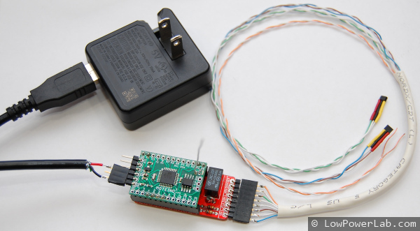
The Moteino running GarageMote needs power, and since you have a plug that feeds your garage opener you can use an old phone charger. If you have a power supply with a 2.1 mm jack, like this one, then you can just plug it in directly in the soldered 2.1mm jack, like I did (see photos below). Any 5V supply is good enough. Cut the cable exposing the GND and VCC wires and solder them to the last remaining 3 pin header – this will plug into Moteino, these photos are from GarageMote R1 assembly:
 |  |  |