

Programming / firmware updates
The firmware for the CurrentRanger is freely available as an Arduino IDE sketch and you can tweak it, customize its default behavior and even make it better.
Easy drag-and-drop firmware updates
The latest firmware is posted on Github. The older R1-R2 firmware is also posted on Github for legacy purposes. Since the release of R3mk4 (and some late R3mk3) the CurrentRanger shipped with a new UF2 bootloader which allows easy backup and swapping of firmware. Hence there is a UF2 firmware file available as well.
To access the UF2 bootloader on the unit, you need to connect the CurrentRanger to USB, and either open a serial console and issue a ‘r’+ENTER (see serial menu page), or tap the RST button on the component side twice quickly (or quickly short the RST pad to GND twice if your unit does not have a RST button), the CurrentRanger will switch to bootloader mode and enumerate as a flash drive that exposes the Current.uf2 firmware – this should be backed up from the unit whenever you plan to replace it or upload new firmware. Also ensure you save the calibration values (from the OLED or USB serial), these values should be loaded after flashing the new firmware (via USB serial menu – press ‘?’+Enter in serial monitor to access all options).
Please note – the active firmware running on the unit will always show up as Current.uf2, but you can overwrite it by drag-dropping a replacement uf2 file (such as newer versions of it that you downloaded from the repository) with any file name and the bootloader will handle the firmware update, which takes a few seconds and then the unit will auto-restart and run the new firmware.
Compiling from source
To compile from source code and upload the firmware you will have to install the following packages in Arduino IDE. First ensure you have the official Arduino SAMD Boards (32-bits ARM Cortex-M0+) boards package, via the Tools>Boards>Boards Manager :

Then you will need the LowPowerLab SAMD boards package, which includes the CurrentRanger SAMD21 board definition. Add the following URL to your Preferences:
https://lowpowerlab.github.io/MoteinoCore/package_LowPowerLab_index.json

Then open Tools>Boards>Boards Manager and install or update to the latest LowPowerLab SAMD package:

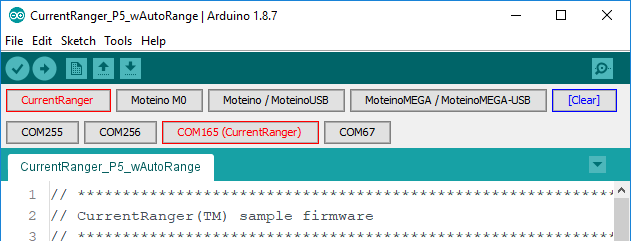
Then once plugged in (it has to be powered ON as well), the CurrentRanger will show as a serial USB device that you can pick as a target in the Arduino IDE, just make sure you pick the correct serial port associated with CurrentRanger from the Tools>Port menu or you may use Felix’s custom Arduino IDE with serial/port shortcut bars add-on:
You will need to install several 3rd party libraries to be able to compile the firmware. Please see the sketch header for the links to each library, they should all be available to install through the IDE’s Tools>Manager Libraries dialog.
Convert HEX firmware file into a UF2 file
If you compiled a HEX version of the firmware and want to convert to/obtain the UF2 equivalent you can achieve this in 2 ways: 1) Upload the firmware to the CurrentRanger and then access the bootloader as explained above to retrieve the firmware as a UF2 file 2) Use the HexToUf2 converter posted in the Github repository.
Older Windows Drivers
If you’re on MAC or Linux you should not need any drivers. Also Windows 10 will probably detect the board as a virtual serial port and assign it a COM port by default without the need of installing a driver. Older Windows versions are likely going to fail to install a driver when CurrentRanger is first plugged in. Click below to get the USB driver and unzip it to your Desktop or another folder. The ZIP file contains a screenshot walkthrough of how to install the driver (shown for MoteinoM0, same for CurrentRanger).
ADC gain and LDO calibration
Your CurrentRanger is calibrated to the measured LDO output during testing, it is a value around 3.3V. Also the ADC gain is adjusted to improve the ADC readings (output on the OLED and to serial logging). These values can slightly change based on load and how long the unit has been turned ON and perhaps other conditions (temperature, etc) – especially true for the LDO voltage. The latest firmware allows to change these values easily via USB serial. The LDO value can be measured on any of the exposed headers (between any GND and “3V” pins). To adjust the LDO and gain, along with other options, access the available commands menu by sending ‘?’+Enter (newline) to USB serial. It is required that you use USB isolation if you do this while measuring a load.
Reset button, manually running the bootloader
There is a RESET button on the bottom side. Although it should not be necessary, you may double-tap the RESET button to enter the bootloader to accept a new firmware upload if you try something that causes the SAMD21 to becomes unresponsive. You know you are in the bootloader if the LPF LED displays a breathing pattern.
OLED I2C Clock Speed
It’s desirable to speed up the clock of the I2C bus when using an I2C SSD1306 based OLED display. Without this optimization there will be more noise on the output when the OLED is connected (visible on a scope only). The “factory” firmware loaded into the CurrentRanger contains this optimization as well as the latest sketch update:
u8g2.setBusClock(1600000); //1.6Mhz i2C clock
SWD programming
To reflash the MCU you will need to access the SWD interface. These pins are located on the PCB as highlighted below. The BOOTPROT fuse is set, this needs to be disabled and re-enabled after flashing the MCU. Any reflashing is done at your own risk and there is no support offered for this procedure. The UF2 bootloader as well as the older samba bootloader are both available in the LowPowerLab SAMD boards package, see the Compiling From Source section above on how to install that.
