

Assembly, Terminals & CAD
It is possible to mount several different type of input/output headers, connectors, terminals and banana sockets:

- 5.08mm spaced thumb/screw terminals – most convenient and quick to use at input, can also be mounted at output
- “GOLD” banana jack/screw terminals – mount on input/output
- low profile banana jack terminals – mount on input/output
- pin headers may also be soldered at various points for easy snap-on DMM probing
- dedicated pin-hole output for low inductance oscilloscope probing
- many other potential options
The “Gold” terminals mount in the smaller aperture of the terminals. A set of 3D-printed half-moon washers are provided to prevent these terminals from sliding in the mounting hole.
Avoid using pliers or any other bulky tool to hold/turn the nut onto the terminal screw, this can damage components on the board. Use a socket/ratchet instead. Avoid excessive force when mounting the terminals, the included hardware that comes with the terminals should help secure the terminals tight into position without a lot of torque.
The lower profile banana jacks will mount in the larger apertures of the output terminals (R2 shown).

The above photo also illustrates the suggested mounting configuration for the terminals, but you may mount in any other way you find useful – the “Gold” terminals mounting only applies to R1-R2 and are no longer included as an option going forward.
In R3 these components are moved back further from the terminal to avoid this.

R1-R2 only: Some of the “Gold” terminals may not flat mount on the PCB, and so it’s recommended to use the included washers to help keep them straight and make good contact.

Here is another mounting example by a user who chose not to use the 3D printed inserts, the extensions of the rectangular washers could be bent like the photo shows or cut off entirely:

OLED header soldering
The OLED header should be soldered neatly if you plan to attach the OLED. Do not solder the OLED directly to the PCB – this has several disadvantages – if it ever breaks, it will be hard to remove and you risk damaging the CurrentRanger PCB in the process. Also, running the CurrentRanger without the OLED will produce a smoother raw output signal. Here’s an example of a nice clean solder job:

3D Printed Enclosure
The CurrentRanger ships with a 3D printed enclosure (R1-R2 in PETG, R3 in PLA). See below for Fusion360 models.

OLED 3D Printed Enclosure
You may also want to pick up an enclosure for the OLED in the shop. This will help protect it and keep it securely attached to the OLED header. This model is also shared on Thingiverse or here on Printables if you’d like to print it on your own.

Fusion360 model (R1-R3)
You can download the parameterized (F3D) Fusion360 R3 model, as well as STL/STEP files in this Github repository. You will also find the older R1-R2 STL file in the same repository.

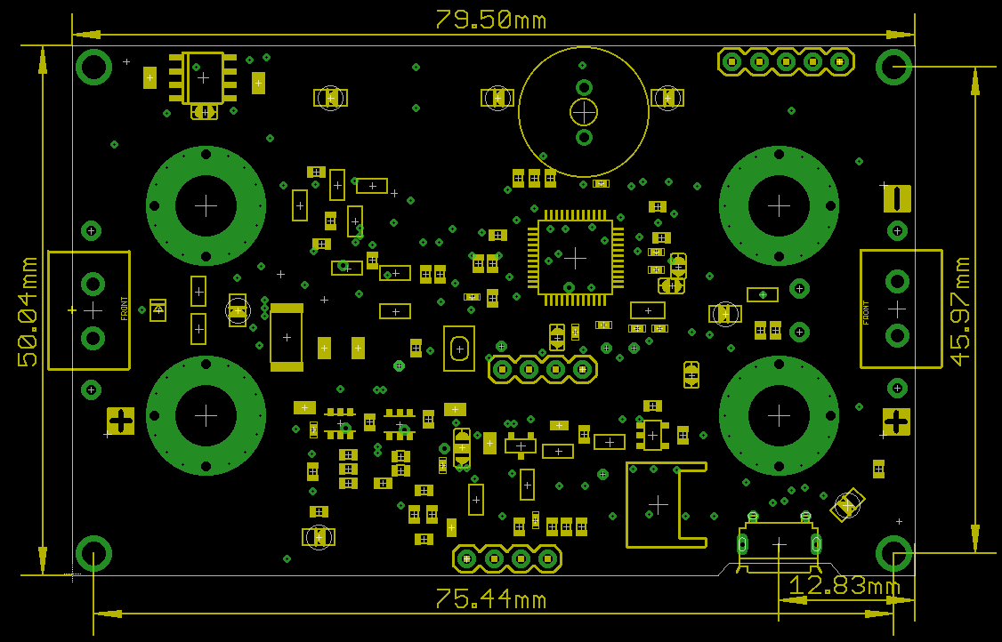
Dimensional drawing
Here are the dimensions of CurrentRanger R3:
Here are the dimensions of CurrentRanger R1-R2:
