What is better than Moteino with a radio? One with two radios, of course.
I had an RF network using RFM12B at 433 MHz. But I wanted to use the higher power capabilities of the RFM69W and RFM69HW. And I also wanted to try out 915 MHz to compare range and object penetration. The problem is that with so many different radios, most nodes I have actually cannot speak to each other. (Clarification: 3 networks, RFM12B@433MHz, RFM69W/HW@433MHz, RFM69W/HW@915MHz - no network has more than 50% of the total number of nodes, therefore the number of nodes any node can communicate with is outnumbered by the number of nodes with which it cannot.) There are a few small RF networks, each on their own standard. I have a good number of RFM12B nodes, and they work fine as they are - I didn't want to spend the time or money to convert them all over to RFM69...
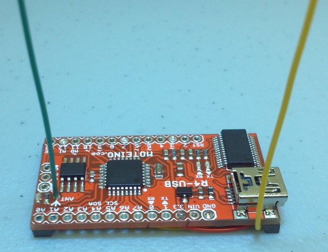
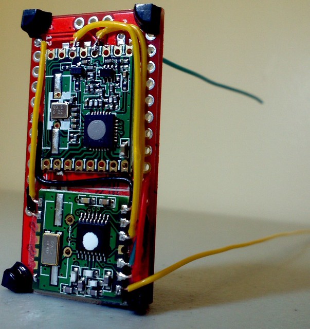
Moteino not being able to speak to other Moteino? Another Moteino to the rescue! Using an R4-USB model with RFM69HW at 915 MHz, it was possible to create an RF bridge, using an additional RFM12B at 433 MHz. The end result is a Moteino that communicates on two frequency ranges, and can translate traffic between two separated networks.
The physical layout of the Moteino R4-USB made it really easy to do this. There was just the right amount of real estate on the radio side to add the second radio with some double sided sticky tape. Then it was a simple matter to solder on a small number of wires to get it connected. There was even some space in each corner for an LRF (little rubber foot), to keep the unit standing upright so that the antennae could stay vertically polarized.
The most difficult part of this setup was really not difficult - it required a small modification of the RFM12B library to work on different pins, since D2 (INT0) and D10 were in use by the RFM69HW. These values were not able to be passed in with the functions, but rather were defined in the .h file, so that file needed to be edited. The RFM12B library did have some options to use pins D8, D9, or D10, but since these were used already by the SPI Flash memory chip, the LED, and the RFM69HW, respectively, I wanted to use pin D7 for the SPI select pin for the additional radio. This is located on a different port than those other pins (PORTD instead of PORTB), so I had to make those edits. The RFM12B library also initializes the SPI pins, so I commented out that code so that the stock RFM69HW/SPI Flash memory combination of the R4-USB could simply stand just as they were, unaffected by this modification. Additionally, to stick with hardware interrupts, I chose D3, which is INT1, for the RFM12B interrupt pin.
from the RFM12B.h file:
  #define RFM_IRQ     3     // changed for dual instance, was 2
  #define SS_DDR      DDRD  // changed for dual instance, was DDRB
  #define SS_PORT     PORTD  	// changed for dual instance, was PORTB
  #define SS_BIT      7     // changed for dual instance  // for PORTB: 2 = d.10, 1 = d.9, 0 = d.8
  #define SPI_SS      7     // changed for dual instance, was 10
commented out these three lines from SPIInit() in in RFM12B.cpp:
//  pinMode(SPI_MOSI, OUTPUT);
//  pinMode(SPI_MISO, INPUT);
//  pinMode(SPI_SCK, OUTPUT);
changed interrupt number at the end of the Initialize() function in RFM12B.cpp:
  // using interrupt 1 for secondary mode.
   if (nodeID != 0)
     attachInterrupt(1, RFM12B::InterruptHandler, LOW);
   else
     detachInterrupt(1);
I could have chosen instead to order R4-USB with RFM12B and then added RFM69HW, and modified the RFM69 library, but there were a few reasons against this. Apart from my familiarity with the RFM12B library, and my comfort level in modifying it, there was also the real estate issue - when ordered with RFM12B, which is a smaller radio, the radio is supplied soldered to the Moteino closer to the center. Then, adding the larger RFM69HW to the back becomes more difficult. Just an observation for anyone who might want to give this a try.
But anyway, that was it. Very simple, with just this simple mod to the RFM12B library, it was straightforward to include it, as well as the RFM69 library, and just create one object of each class, and use them normally. This bi-directional bridge node just alternately listens for traffic on the two radios, and forwards any traffic it is directed to forward to the other RF network. It does only this one task, and I chose the USB model so it can just stay powered all the time, so as not to spend any time on low power sleeping. Constant network availability is the priority.
To demonstrate that this was all working, I created the following setup:
1) A standalone R4/RFM69HW test node @ 915 MHz (Node A)
2) A standalone R2/RFM12B test node @ 433 MHz (Node B)
3) This RF bridge node with both radios on the two different frequency ranges (Bridge)
4) My
Keurig B60 coffeemaker, which has a Moteino R2 with RFM12B radio @ 433 MHz (B60)
I had previously created Node B to test the B60, so I just modified it to also be able to send a message to Node A, through the Bridge. Node A accepts any traffic from any source, and simply reverses any buffer it receives, and sends it back in an ack. Additionally, it can send commands meant for the B60.
In the following image, we have Node A on the left, and Node B on the right, with the Bridge in between. Node B is polling the B60 for status, to see if it is on, if the water is hot, etc., every 6 seconds. The number transmitted after the status is the value of millis() on the B60's R2 Moteino. Node B is just monitoring the B60, and is independent of any Bridge communications for this test.

When the test starts, the B60 is off. Node A sends a command to the Bridge, destined for the B60, to turn the coffeemaker on. The Bridge receives this command on 915 MHz, forwards the command on 433 MHz to the B60, receives the ack back from the B60, and relays that ack back to the originating Node A. The coffeemaker turns on, and the independently polling Node B directly gets word from the B60 that it is now on.
The test in the other direction doesn't involve the B60, but it is still just being polled by Node B. In the following image, Node B is the originating node, and sends a message to the Bridge, intended for Node A. The relay occurs, Node A reverses the buffer and sends it back through the bridge to Node B.

That's it, it works!


