SwitchMote R2 coming soon

UPDATE: It is now released (release notes). Assembly & guide is here. Kit available at the shop.


You asked and I’ve listened.
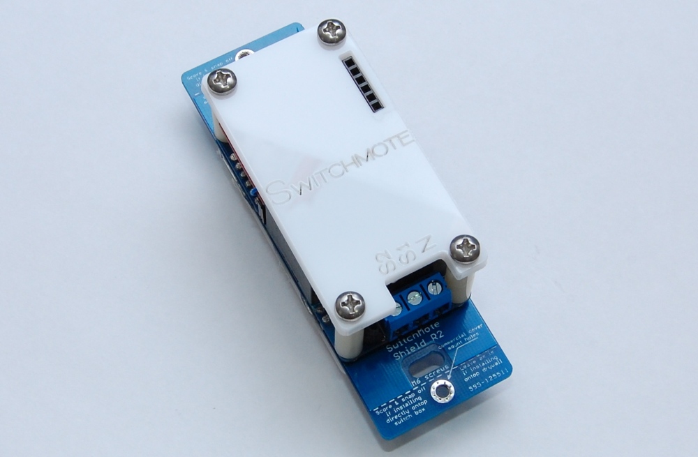
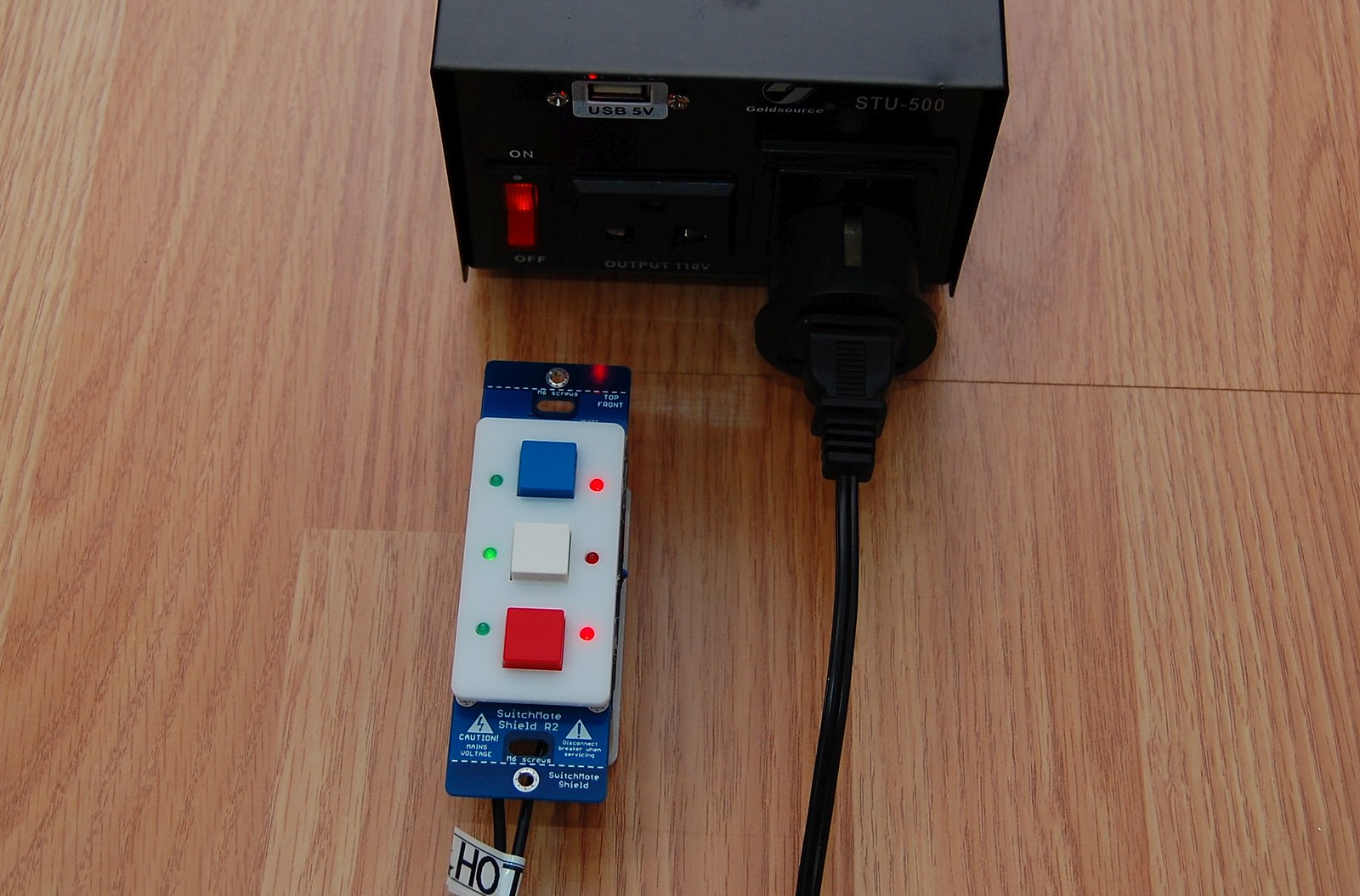
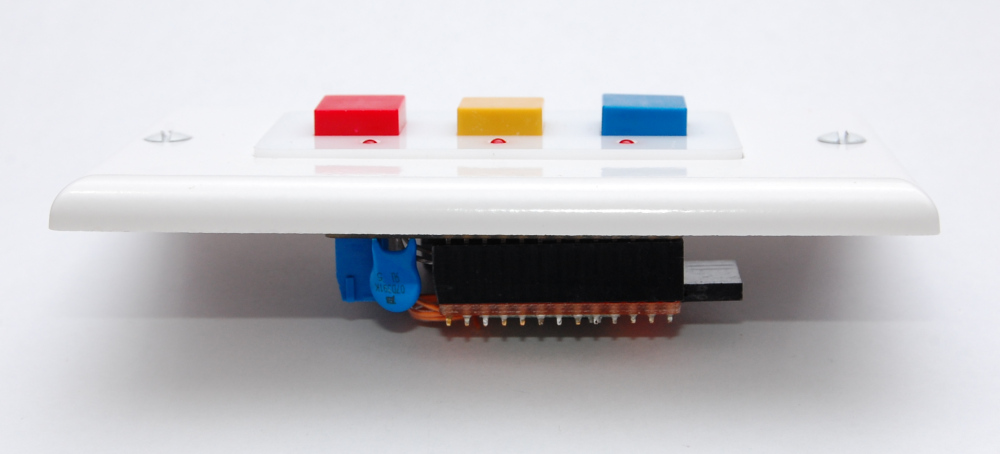
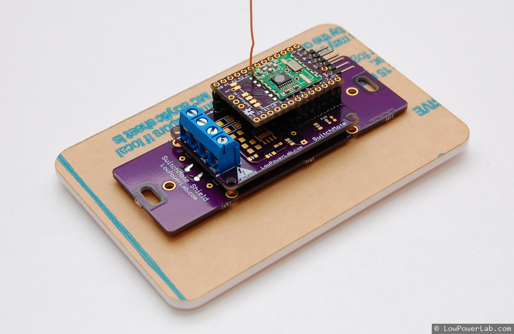
SwitchMote R2 is coming soon as a 100% kit, and should address most safety concerns and shortcomings of R1. I gave up the previous non-isolated design because of different considerations. The switching regulator was not able to work reliably beyond 185V from a half wave rectified input. Then lots of people talked about isolation and supporting loads higher than the 100W on R1. Well I came up with a design that is only slightly bulkier, and is fully isolated (3kV) through a UL certified PSU that supplies 5V @ 400mA for the electronics, uses a very compact coil relay with up to 5A @ 250V load. The design is also much more balanced and I’m happy with the result, the back cover plate uses 4 mounting spacers+screws, allows programming through the FTDI female connector. You can solder your wires directly to the PCB if you are required or you can use the traditional screw terminal. And lots more to talk about but more details will be included in the assembly and usage guide. And yes it works at 240V, doing timed testing right now:

The non-isolation part was of concern because of liability and because I am not a huge company to back it up. To prove my point, look at the tear-down photos of this IRIS switch, it uses a non-isolated design, will you buy it? Continue reading

SwitchMote source code released!

The source code for SwitchMote is finally “done”. As always, consider this a beta release at best, you should always check the github repository for any updates. There are 2 parts to configuring and programming a SwitchMote.

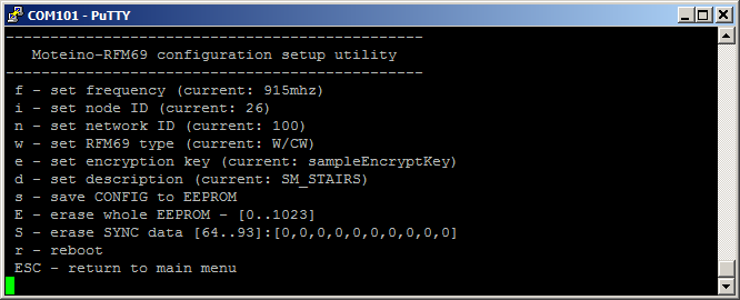
SwitchMoteConfig sketch, which needs to be loaded and used once, after assembly and before SwitchMote installation. This sketch is meant to help setup the essential parameters of the Moteino in the SwitchMote such as frequency, node and network IDs, RFM69 type (W or HW), encryption key, description, and some other utilities that may be extended in the future. All these parameters are then stored to EEPROM and will not be dependent on hardcoded values in your sketch.
This is especially useful when you have some nodes with RFM69W Moteinos and some with RFM69HW. It’s hard to keep track of all the transceivers settings. Additional settings could be added, like power level, bitrate, etc. Keeping the configuration with each node is most efficient in applications like SwitchMote. Setup once and forget!
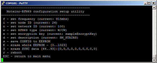
SwitchMote sketch is the permanent sketch that will get loaded on your SwitchMotes. Note that this sketch will read the EEPROM configuration that was setup with the SwitchMoteConfig sketch mentioned above. This sketch does several things.

  • keeps track of which buttons were pressed, and manages the modes of operation
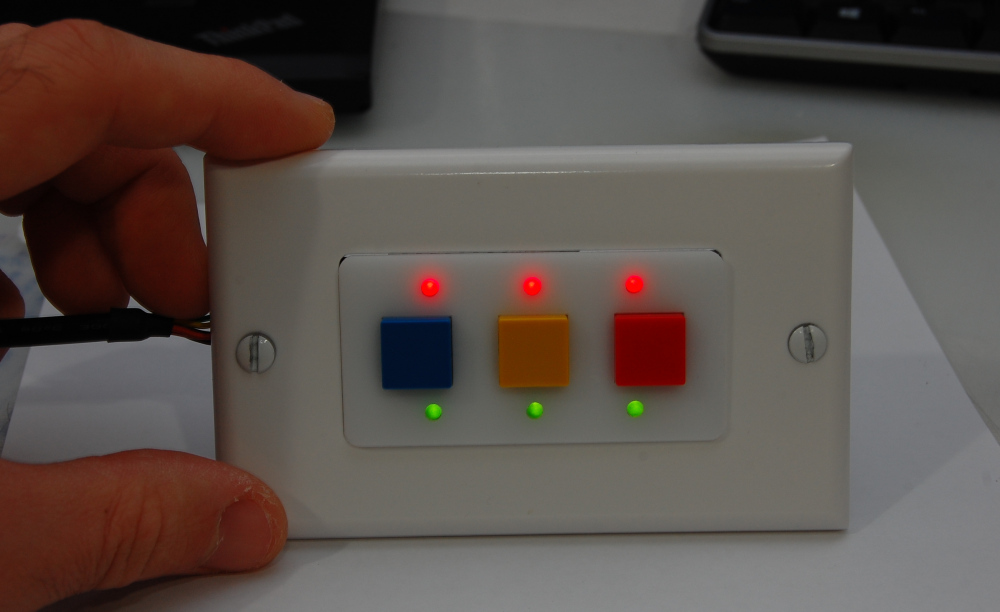
  • any button can be in ON or OFF mode – reflected in GREEN or RED led status
  • listens for BTNx:y tokens, to put button x in mode y, x={0,1,2}, y={0,1}
  • listens for SSR:y tokens, to turn the SSR on or off and the associated button in that same state (reflected by the LEDs)
  • if the button associated with the relay (SSR) is pressed then the SSR is turned ON or OFF depending on the mode that button transitions to
  • if a button is held pressed for at least 3 seconds (configurable) it enters SYNC mode, explained below
  • if a button has SYNC data it will notify the remote SwitchMotes to virtually “press a button”, and transition that button to the mode specified in the SYNC data
  • if any button is held pressed for at least 6 seconds (configurable) it erases the internal SYNC data in EEPROM. This could be modified such that only the SYNC data associated with the pressed button is erased, not the entire SYNC data
  • notifies the gateway, if any present, that a button was pressed

Note that SwitchMotes loaded with this sketch will work independently and with each other without the need for a network gateway or coordinator. A gateway is by default notified but the feature can be removed if not desired.

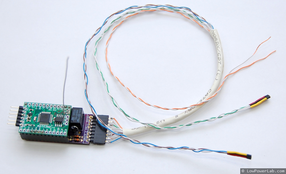
Also note that a SwitchMote can work without a relay, in which case only the neutral wire N and a hot wire to either one of S1/S2 is needed. In this case the SwitchMote can just act as a controller for other SwitchMotes or be customized to send other commands to other Moteinos. For instance you could open/close your garage (with GarageMote). The sky is the limit of what you can do.

Further details of the SYNC feature and how to use it are documented on the SYNC mode section of the SwitchMote page. Please refer to that page for any updates and latest information on SwitchMote.

Happy switching & sync-ing!

P.S. This code was released for RFM69 transceivers only because of huge growing interest in these line of transceivers and diminishing interest in RFM12B. You are welcome to port this to a RFM12B implementation as long as you keep within the boundaries of the CC-BY-NC-SA license.

Wireless programming a SwitchMote Moteino

I’m close to being done coding the SwitchMote, I think the code will be released tomorrow. I’ve been testing the code on the SwitchMote here in the lab because I can physically interact with the buttons on it. Needless to say, every time I want to upload the new firmware I cannot disconnect the breaker, unscrew the wall plate and the mains wiring, detach the unit from the wall to be able to upload through FTDI, that would be awful.

Enter wireless, over the air, magic, programming of Moteinos.
I’ll just say that it comes in very handy when your project is in the wall!

I’ll cut this short and let you watch how it happens, too bad the flashing LED is not very visible on the video while upload is in progress:

One note to mention is that I’ve recently patched the wireless programming library to shift frequency up by 8Mhz during upload so the heavy RF traffic would interfere less with the rest of the network packets. Also I added an option to use another LED to be flashed during upload – handy for SwitchMote which has a bunch of LEDs on the front panel which are all on other pins than the default D9. I’m also planning to experiment with increasing the bitrate during the upload, maybe double it, and see how much faster and reliable that is. But that might prove tricky since several other settings depend on that, so all settings have to be changed back to what they were after the upload is complete.

SwitchMote project update and demo

I put together a quick video to show the progress of SwitchMote and a simple demonstration of how it works and how it can be used in home automation. My goal is to offer a smart wireless light switch controller that allows syncronization with other units independently (without the need of a gateway/coordinator) to create light scenes, and increase the usability of a regular light switch.

Continue reading

SwitchMote – one step closer to reality!

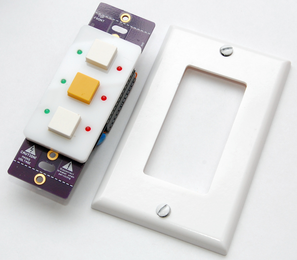
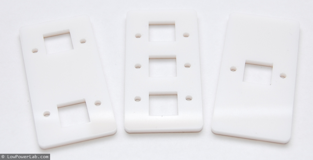
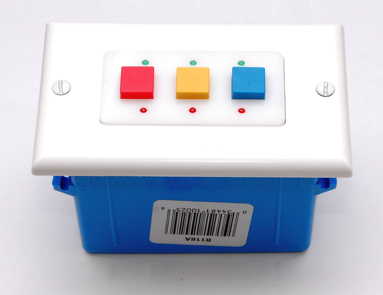
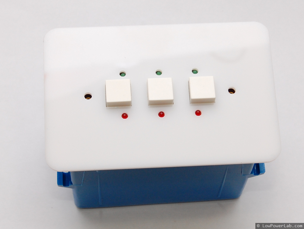
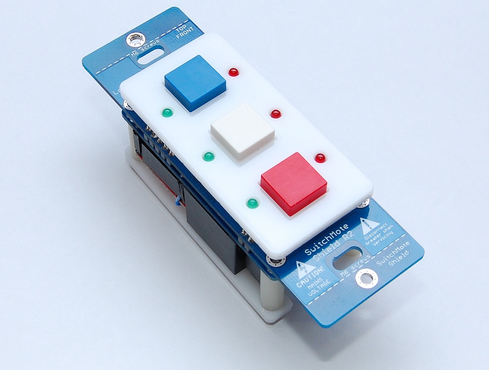
Just got another batch of SwitchMote and SwitchMote Shield PCBs from OSHPark the other day and I put one together for a test run. In the meantime Kris K has suggested I try another type of cover for SwitchMote. I think his idea was great and today I lasered a few of these covers that are meant to fit in the cutout of a regular rectangular light switch and they turned out very nice. This way people could replace the light switch and keep the original cover, or upgrade to a rectangular cutout cover (HomeDepot has all sorts of light switch covers, even paintable if you’d like to blend them with the wall color). The acrylic is also available in different colors from different sources but for now I’ll go with the usual white I’ve been using before.

The button caps come in different colors so I got a few samples to try out. I think blue, red, yellow and white should cover most needs. The green I found was pretty washed out, didn’t really like it, but I’ll keep looking. Here are a few build photos, and more in my flickr SwitchMote set:

More people started asking when this will be available. I’m already producing custom versions of this and I’m trying to get as much testing done as I can. It is mains power stuff so I’m taking this seriously. This 3rd prototype of SwitchMote includes a varistor and trace fuses for added safety against transients and overloads. I need to develop the firmware stack for this and think of how I want SwitchMotes to interact with each other. The SwitchMotes will need to be wirelessly re-programmable when the need arises so users would not have to disconnect it from the wall when they want to update it. But I want SwitchMote to be pretty autonomous. I will install and try a few on my own, planning on replacing some 3 way switches and some outside lights I’d like to turn ON/OFF from the master bedroom. Fingers x-ed. But so far so good, all the buttons work, the LEDs glow nicely in the dark and are very visible even from a distance, and mechanically the unit is pretty much where I want it to be. This setup should fit easily in any standard switch box.

Will follow up with details on progress, stay tuned!

Wishing a very Happy Holidays Merry Christmas and a Happy 2014 to everyone reading this blog!

What’s up at LowPowerLab?

Haven’t had much time to blog lately, too much stuff going on all fronts. That’s not to say LowPowerLab is idle, no no…. On the contrary the shop is keeping me busy and I have a few new projects I am working on. I am trying to bring a few kits to fruition.

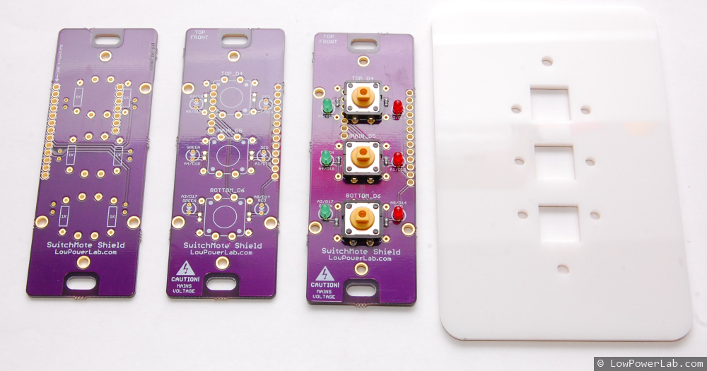
First and foremost I’ve spent a lot of time developing an integrated solution for SwitchMote. I want this thing to come to life and just be awesome, I think I’ve spent way too much time on it to just let it die. I now have another prototype including a shield with 3 user buttons and 2 LEDs per button, which can all be used in any way, or left unpopulated if only 2 or 1 buttons are desired for a light switch. The point of having multiple buttons is being able to control or synch with other SwitchMotes or … do anything else you want like say … interact with GarageMote. I’ve managed to get a cover plate also that will be mounted on the wall to cover the switch box. I used the same diffused white I laser cut for the MotionMote project. I like that diffused white a lot, but there’s many possible colors on inventables.com to choose from. For now I am continuing to develop this project, write code, adding some basic mains protection and getting all the physical engineering of this thing right. So far I’m pretty happy, it’s a pretty good improvement over the first prototype I had:

Continue reading

Switching mains/lights with Moteino

Here’s a peek at another project I’ve been working on lately, SwitchMote. It’s a compact shield for Moteino that has a mains switching power supply and a solid state relay to drive a mains load. I’ve designed this to work for lights. The idea is to replace a single regular light switch with this so that I could control lights from the home-automation controller, while allowing it to be operated manually as well. An LED indicates the status of the light/load (LED on when light off).

Continue reading

RaspberryPi home automation gateway – Hardware and Demo

UPDATE: An updated version of this gateway install guide is published here. The rest of this post is kept here for legacy purposes, some links to source files might be obsolete or not work any longer, please see the linked guide above for the latest code and walkthrough.

In this last part of the RaspberyPi home automation gateway series I will show an example of hardware implementation that talks to the RaspberryPi secured realtime home automation gateway, and share the firmware source code.

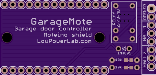
GarageMote is a garage door controller shield that can be used to remotely control a garage door from anywhere on the web or from your smartphone.

GarageMote was created for several reasons. Mainly because as I’m adding more Moteino based home automation devices around my property, one of the nice things I wanted to be able to do is control the garage door remotely. It’s become so routine to close the garage door when I leave from home that sometimes when I’m already 5 or 10 minutes away I wonder if I actually closed it. And so I want to be able to check the door status and close it if it was left open by mistake, without having to drive back home. Or maybe it’s useful to be able to let someone in without giving them the garage code every time.

Continue reading

RaspberryPi home automation gateway – Setup

In this third part of the RaspberyPi home automation gateway series I’d like to present the RaspberryPi software stack that will allow a secured realtime webserver-websocket gateway to your home automation project.

As a webserver I decided to try Nginx. I’ve previously used Apache which always felt a bit slugish and had a large disk and memory footprint. There are many bechmarks that contrast webservers performance, here’s a nice one that focuses on RaspberryPi, and it includes Nginx and Apache.

The stack will be a webserver (Nginx) and a websocket server (Socket.io). The websocket will be proxied through Nginx, and everything will be encrypted with SSL and authenticated with auth_basic. A bunch of other things need to be setup and configured to make these work nicely together. Continue reading