
UPDATE: The issues are now resolved. See this post for updates.
Hello folks. I’ve been trying to develop a new Moteino variant, one based on the ATmega1284P chip. I dubbed it Moteino MEGA since it has significantly more memory, IO and functionality than the 328P. All went well except when trying out with RFM69 radios, I can only transmit but not receive. So I’m writing this post in hope that someone else tried the RFM69 library with an Atmega1284P and has some tips to spare. I’ve been using the maniac-bug 1284p arduino core and from all I can tell the external interrupts are set correctly in this distribution. I used my Node sample sketch with appropriate RFM69 settings. The receiver is a regular Moteino. The Moteino MEGA is calling sendWithRetry(…) which sends the packet 3 times until it gives up. All three packets are received at the gateway, and all 3 ACKs are sent back. I modified the RFM69 lib to attach the interrupt routine to INT2 if it’s a mega1284p. But the interruptHandler() in the library does not trigger on the Moteino MEGA. I pulled the logic analyzer and it looks like the INT2 (D2, wired to RFM9’s DIO0) goes HIGH when it’s expected (and stays HIGH quite long, weird), but the interrupt routine is not called. That’s where I’m stuck. At this point I’m not sure where the issue is but I tried a simple interrupt handler program which seems to trigger just fine:
boolean interrupt = false;
void blink()
{
  interrupt = true;
}

void setup()
{
  pinMode(LED, OUTPUT); //LED=15
  attachInterrupt(2,blink,RISING);
  Serial.begin(115200);
}

void loop()
{
  if (interrupt)
  {
    Serial.print("X");
    for (byte i=0; i<10; i++)
    {
      digitalWrite(LED, HIGH);
      delay(25);
      digitalWrite(LED, LOW);
      delay(25);
    }
    interrupt = false;
  }

  digitalWrite(LED, HIGH);
  delay(500);
  digitalWrite(LED, LOW);
  delay(500);
}
I hope to get past this hurdle and be able to release this new board since some people asked for more memory and IO. I have yet to port DualOptiboot to it but I need to solve this mistery first. Maybe there’s a bug in the 1284P core. Or something I’m omitting, just out of ideas right now. If anyone has an idea why this is happening please let me know. Thanks!
UPDATE: I tried an RFM12B with the atmega1284P and the good news is it works with my RFM12B library. The bad news is that after about 15 minutes of running the sample send sketch it stops working and the atmega1284p appears to be completely nonresponsive, even to the AVR programmer. I’ve tried this with 2 chips, both died after about 10-15 minutes of continuous transmission. So I’m baffled. The power supply is the same as the regular Moteino – 3.3V and nothing heats up, radios wired the same except to INT2 instead of INT0, same 16mhz resonator. Chips were from digikey so I don’t think they are counterfeits. Any hints anyone?
I bet it’s a software problem, but if you think it’s not, it could also be an open power or ground pin, or it could be a short between two pins?
Is not the 16MHz out of specs for 3.3V?
Yes it is. Should not die like that though… I will try at 5V next time around.
16 MHz @ 3.3V is out of spec for the 1284p, perhaps it is less tolerant of this than the 328p ?
Yes it is. Should not die like that though… I will try at 5V next time around.
Did you try slowing down the I2C clock?
I wasn’t using I2C, you mean the SPI? It worked fine since the packets were transmitting on the RFM69 and receiving/transmitting on RFM12B. The problem was with the interrupt not triggering. Maybe it’s the clock speed. I will need to try at 5V and/or use the 8mhz internal resonator.
Try turning the transmit power level down to 1, and/or put a 50 ohm load on the radio. RF may be getting into the circuit and confusing the processor. That’s solved a few weird lockups on the motinos for me.
Noted, thanks!
I try to use the similar 2560P at 3.3v 16Mhz and it’s not stable, it work’s fine with small sketches, but not with big ones.
By the way, what if you add some more stuff to the Moteino Mega, something like an RTC a cheap one like MCP7940N and an improved FLASH memory.
I suspect it’s the overclocking at 3.3V, though the mega328 has no such issues.
You can add the extra devices externally. Not everyone needs an RTC and big FLASH. If you want a custom FLASH just get the moteino without it and add your own. Big flash mems are SLOW though…
Not familiar. He doesn’t support the atmega644/1284p.
Hmm.
Cosa supports the Microduino-Core+ which I believe to be based on the 644/1284p chip…
Either way, I highly that you recommend you peruse his fully-featured and well-documented platform if/when you get a few spare moments. I have converted all of my arduino projects to Cosa. 🙂
Sounds good, but I will let you convince my audience to switch over too 😉
I believe these chips require both VCC and AVCC to be connected. AVCC is running the ADCs. It appears that you INT2 is on a pin with ADC functions as well. I would make sure that AVCC and AGND are connected. It is possible that Port A was self-powering from the pullup on INT2 and this worked for awhile until the chip was damaged.
Can you check the oscillator with a scope? Is the clock running? If the clock is not running and the device is not in reset, then swap the resonator. You can also steal a clock output drive from another AVR to drive the input of this board as a test.
The chip programs through JTAG. Does JTAG even respond? You can scope the TDO line when attempting to talk to the chip. If TDO does not toggle, then the chip is dead.
Thanks for the tips, however INT2 is on a digital pin, not analog. The pin also is AIN0 which is an analog comparator, but is setup as external interrupt. Not sure what you meant by pullup on INT2, there is none since it’s an active HIGH interrupt, and it’s not associated with port A. JTAG was disabled with fuses. Something fatal happened, not sure what though. The chip appears dead and non responsive to anything. I wonder if overclocking at 3.3V/16Mhz can damage it. Or as somehow RF “leaked back into the circuit” as someone suggested, but I would not expect that from RFM12B which is much lower power than RFM69.
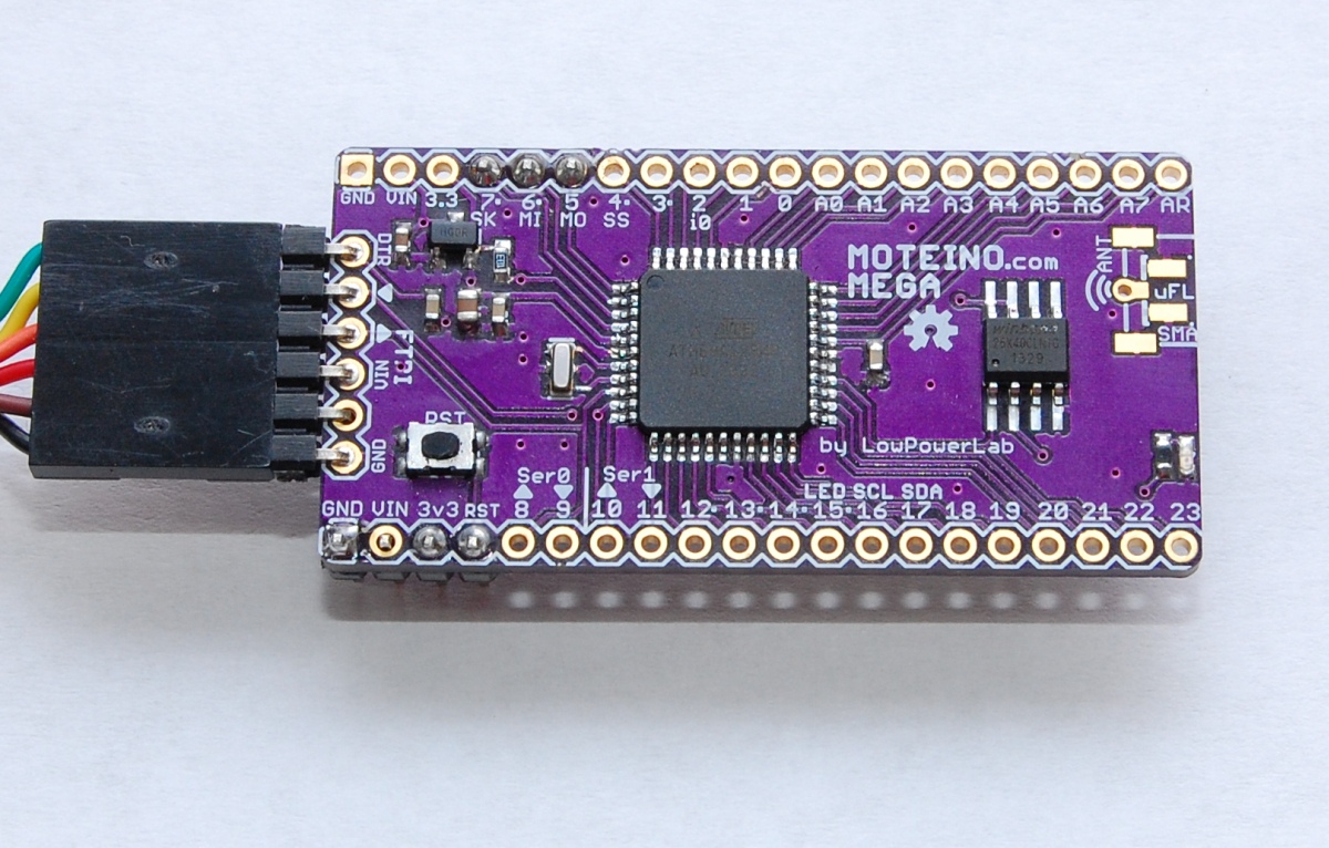
Looking at the picture of your board, it appears like AVCC may not be connected. I would humbly suggest a re-read of the datasheet. The datasheet I saw on the web mentions that AVCC should be connected to regular VCC if you are not using the analog stuff. I remember this causing problem in earlier Mega chips.
Another thought is that somehow your fuse settings got scrambled. Perhaps due to RF or due to insufficient power supply recoupling or the AVCC issue. There are several examples of using one AVR to provide the programming sequence to unlock another AVR. The secret is that you have to boost the reset pin to 12V to get into a special programming mode. Have a watch at the video at the link below.
https://www.youtube.com/watch?v=t6WIYvb5dos
AVCC and VCC are connected, maybe not obvious in the photo. I’ve unlocked atmega328s with mightyOhm’s shield, but they are not always salvageable. I am waiting for more chips to try.
Sounds like D2 goes HIGH while interrupts are explicitly disabled.
Try to :
– disable all other libraries (like SPIFlash)
– use send() instead of sendWithRetry() which continuously enables and disables interrupts
Felix,
Playing with interrupts is always a headache and thinking about how to use them need some attention.
First any variable used in isr should be declared as volatile to avoid compiler optimization on then and potential issues.
Also avoiding long stuff on isr such as serial.print or printf and keep isr as short as possible and do treatment in loop (this mean think how loop should be coded to correctly interract with isr).
And when in loop you’re using variable that can also be used in interrupt encaplusate treatment in loop on this var with cli and sei.
Example imagine a float var you setup in loop with
Myvar = 12.34;
Assembler code doing this can take more than one instruction and if you are interrupted between the instruction and you read the var in isr, the value readed can be not reliable because the main affectation in loop is not finished.
This is an advice always true when using interrupts but may not be the cause of your problem.
I suggest until your problem is solved to run the mega at 8mhz (if you supply it with 3v3) or supply it with 5v for 16mhz (take care with rfm power but you know that)
Can also be bad contact with pcb sometime it happen.
I’m sure you will find the solution, it should work but r&d always bring us problems like that when we’d like to spend time on more productive things
Let us know if you find the solution.
Charles
Felix,
By the way on which irq pin is connected the rfm12b ? Int2 also ? If so the Rfm12b library need to be tweaked (I needed to do it with my dual rfm2pi gateway with a rfm12b on irq1 and rfm69 irq0 on same board)
The code rfm12b:control assume int0 whatever value you set RFM_IRQ in rfm12b.h file !!! Took me some headache to find.
I have already modified the library to handle irq1 or irq0 on atmega328 with some other tweaks such as custom cs pin an reliable reading of analog rssi of rfm12b wiring the rfm12b arssi pin to analog pin.
I did not put code on my github because it’s currently under testing but could be fine to have some people testing it 😉
Charles
Charles – it’s on D2/INT2. I made manual changes in the library for this board. And yes the IRQ handler has volatile variables. The problem is probably with overclocking. Thanks for your input.
I hadn’t seen that you’re creating a MEGA mote and have already ordered MEGAs and am creating a shield for the RFM69 radio now. I’ll be watching to see your solution in case I have the same issue. If I don’t have any issue I’ll let you know after I complete the shield.
Brian
attachInterrupt does not have the same meaning on mega’s version than on 328P. You need to say which pin to attach. Typically, attachInterrupt(2, …) means looking for intr on pin D21 or D0 (I don’t remember which one exactly).
Please refer to http://arduino.cc/en/Reference/attachInterrupt
You can also try to wire the interrupt pin to any other pin and at least one will trigger the interrupt.
Any further news on this Felix ? The extended capabilities of this device is something I could really make use of. I have a HY28B serial touch display hooked up to a R3 and working well, however the memory becomes very tight when trying to implement different fonts for the display….
I spent some time last night with my second batch of protos and I am happy to see much better results. I think I will get some production PCBs in my next order and offer it for sale in the shop. Stay tuned for updates. FWIW I googled HY28B and found a video you posted and I noticed the Moteinos 🙂