When I built the first revision of Moteino I had to come up with a way to program and test them quickly without having to solder the headers. I saw how others built complicated jigs for this purpose with all kinds of features, so I wasn’t very excited to do something like that.
It needed to be quick and simple (without the ‘dirty’) and also without a lot of waste – spring loaded test probes (aka pogo pins) are expensive and when revisions change sometimes the positions/function of the holes change as well and I didn’t want to spend a lot of time/$ making a jig. So I just stacked two of the same PCBs as the target and used pogo pins to hold the PCBs together (or rather the PCBs to hold the pins aligned and leveled). That worked great, with one hand I could hold/press the target PCB on top of the pogo pins, with the other do the programming.
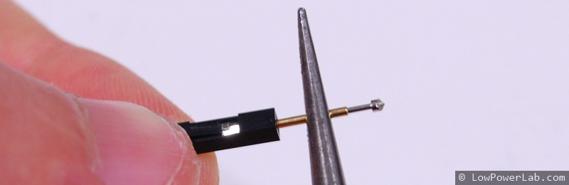
So what are ‘pogo pins’?
They are small cylinders with a piston tensioned by a spring that pushes it out and they come in all sorts of lengths, thicknesses and tip configurations (they actually have codes for each tip type and length), a picture is better than words:

Other PCBs required testing so I built quite a few such testing jigs, here are a few examples, notice the simplicity:
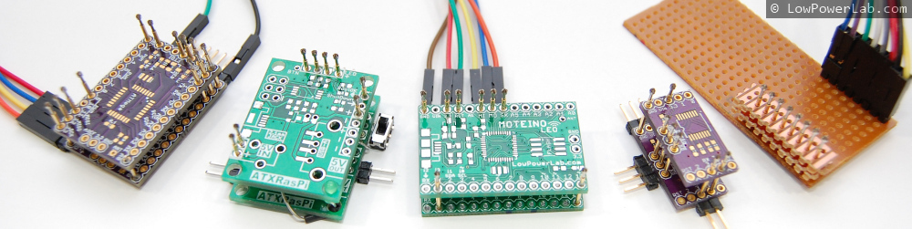
The rest of this blog entry is a guide to making jigs like these. Your final solution and it’s capabilities is only limited by your imagination. For instance you might test if a pin goes high by soldering an LED, or turn a pin HIGH/LOW by soldering a switch.
One issue I had with some boards that have a standard ICSP programming header is that the programmer will not supply power through it. That makes a lot of sense but also it meant I needed a way to power the boards separately. The jigs made that easy – add spring probes on the power pins and then solder regular headers on the bottom and connect power that way.
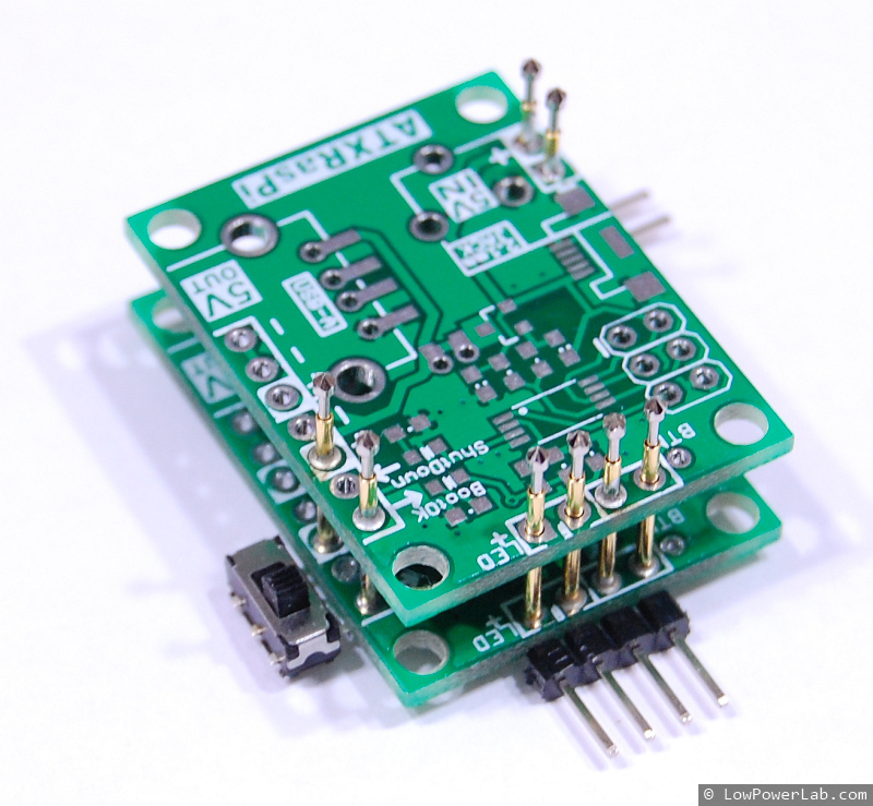
Some boards only require programming or it’s easier to do the programming and testing in two steps. ATXRaspi comes to mind. So I decided to make a dedicated header for programming ICSP headers, which could also power the target board.
Here’s an illustrated guide to making something like that. I took pictures while building a jig for ATXRaspi R2.
You’ll need some basic tools and materials:
- pogo pins
- jumper wires, regular and long pin male headers
- PCBs identical in layout to your target PCB, or stripboard if your PCBs have 0.1″ spaced pin holes
- pliers, soldering iron, tape
- programmer

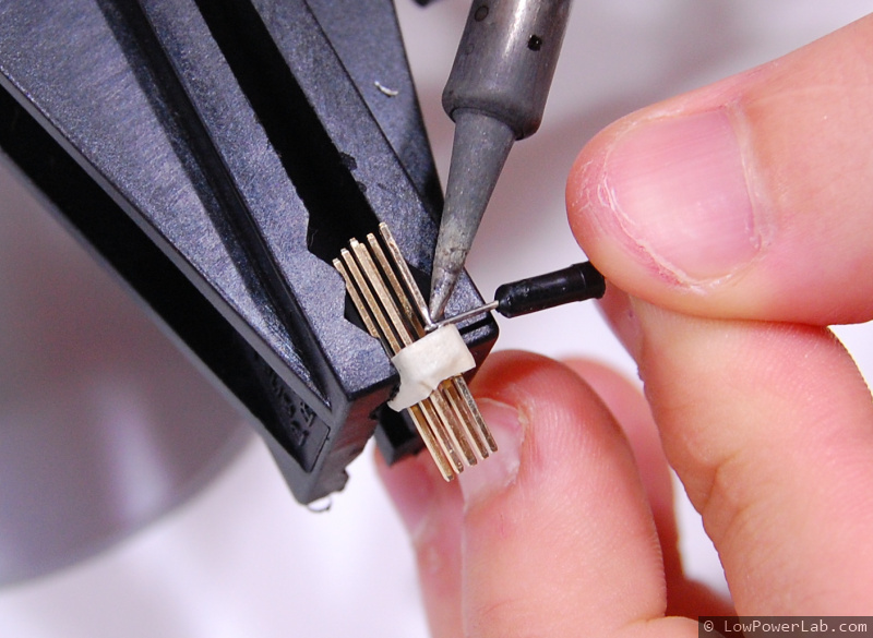
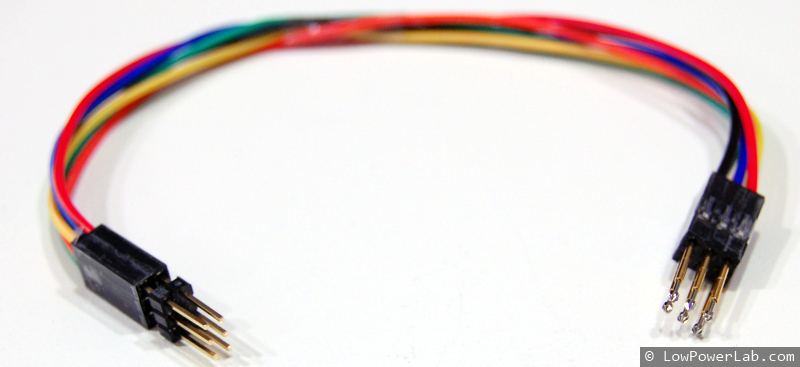
- First I took 6 female jumper wires and inserted the pogo pins in each of them (gently push them in with some pliers). I use the colors to know which wires are what function (black/red:power, yellow:miso, blue:mosi, orange:sck, green:reset).
- Take some long pin headers and break off two 1×3 sections, and insert them on the other ends of the jumper wires:
 Use some tape to group them together:
 And end up with something like this:
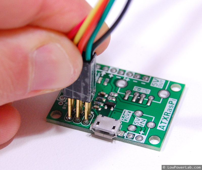
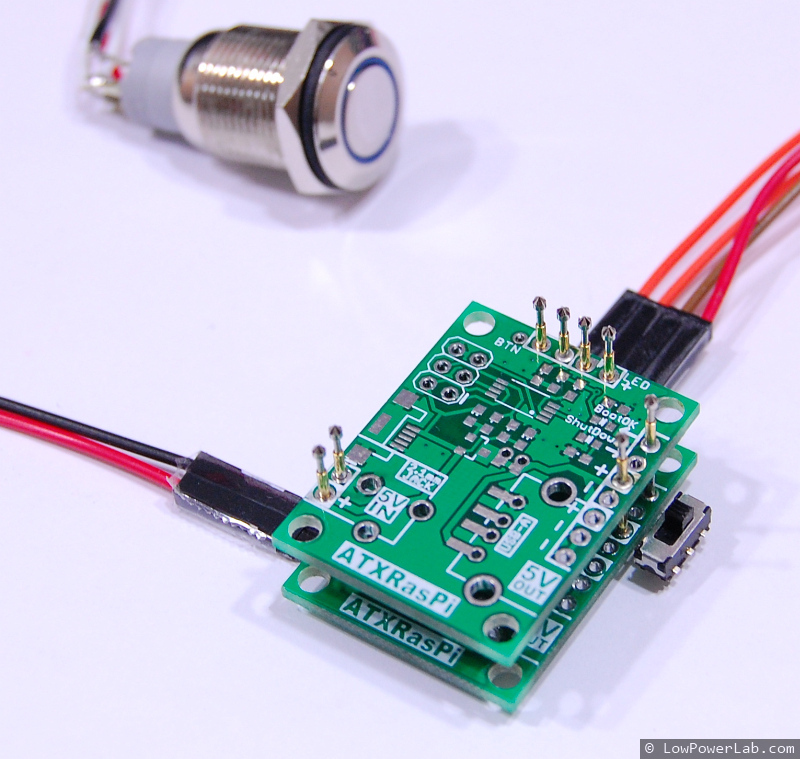
- Solder separate power jumper wires (to provide power to the target). Then use the programmer to set the fuses and upload the flash image:


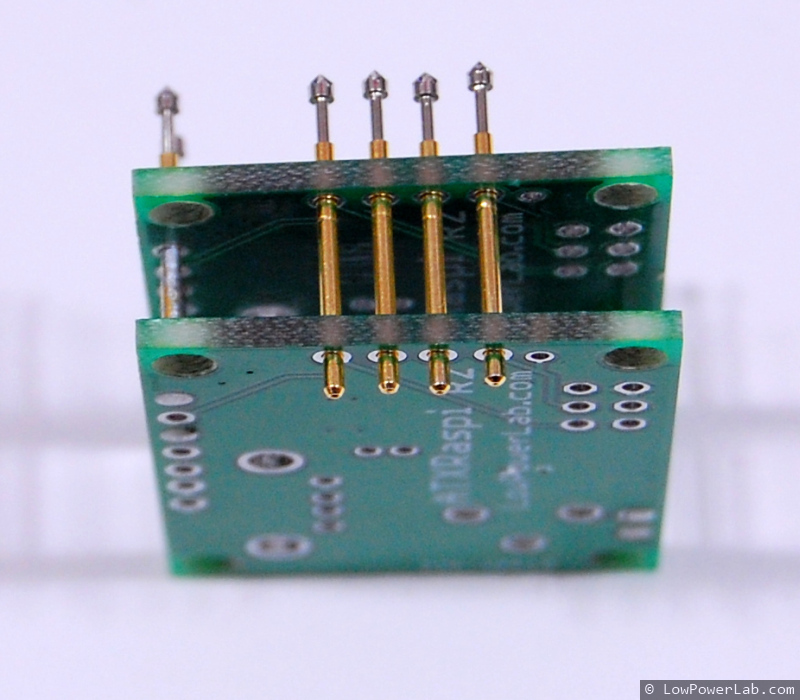
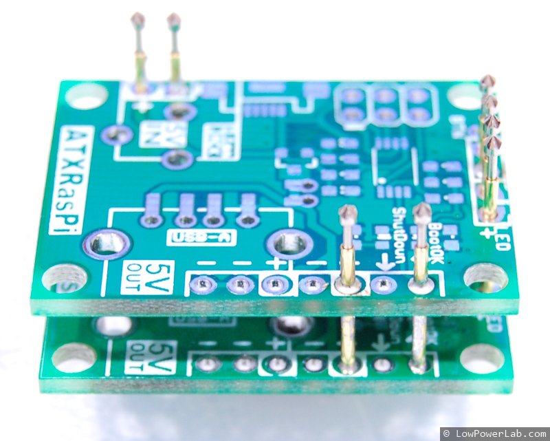
- For the testing jig, I took two PCBs of the same type, and the pogo pins are inserted in the relevant positions, also making sure the boards are balanced for pressure (if all pogos are on one side they might break, so just add one or two on the other end to keep it balanced if you need to). I solder the bottom of the Pogo pins flush with the bottom PCB, and then solder solder the top PCB with the pogo pins’ notch inside the pin holes (that’s to strenghten and prevent them from breaking at that point – they will break eventually if you don’t do that). I finally solder male headers on the bottom for connections I care about and also any other peripherals that help me test/debug (like switches, LEDs, etc):


- Done!
The jig is ready for testing. For this board I actually added some more stuff to it later on (note the LED), but here’s how it works: