RF range & performance testing in a concrete building

I needed a quick and easy (and slightly more professional) way to measure RF performance of the typical RFM69/RFM95 low power transmitters, at a remote location where a prospect RF sensor network would be installed. Here’s a video explaining the devices and what’s involved, the rest of the blog has more details, the code and links you might be interested in.

In the past I ran range and performance tests of RFM69 radios in various types of applications to gauge how it might perform. I know it does great in medium/large residential homes with many walls and gateway in a corner of a concrete basement, while nodes are transmitting from inside and outside the building 100-200ft away. It also works great in typical industrial buildings (usually metal) with lots of equipment and obstacles. Of course in practice we follow some basic RF principles to ensure our small antennas are oriented decently and signal not degraded by incorrectly crammed or wound inside enclosures.

At this location we had an unusual multi level heavily reinforced concrete building. I did not know what to expect – would all the concrete and rebar act as a faraday cage and totally block signal from an outside sensor to an inside gateway? Or would performance just be poor?

I assembled a MotionMote – which runs on a CR123A 3V lithium, sipping ~2uA. These batteries are great for temperature extremes, yielding a stable and deterministic discharge curve, and they can last for many years on an ultra low power node such as the MotionMote.

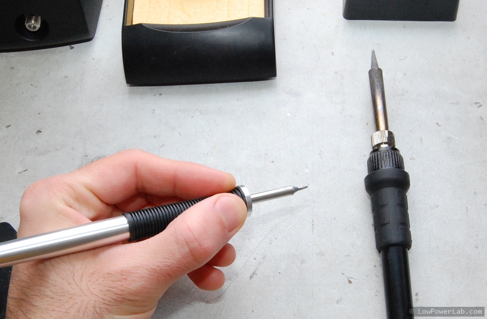
RFGateway is my go to board for setting up a RaspberryPi as an RF gateway. It plugs straight into a Pi’s USB port and I would normally use an SMA dipole antenna at the gateway end of such an RF network. The video shows how I soldered a helical to an SMA male connector to mate it to the RFGateway’s SMA-female connector.

The RFGateway’s SAMD51 processor clocks at 120mhz, plenty fast for handling packets from a very large RF network, while doing floating point and other memory operations. It has a small header convenient for an I2C OLED. Also for this evaluation I just used a LiPo battery plugged into the power header, only connected when USB is not plugged in.

Any compatible transceivers can be tested, but for this application RFM69HCW was used as I prefer it for all my RFM69 based applications.

To run the test I placed the small transmitting node (MotionMote) in a fixed position and walked away around the property and inside the building in the areas of interest with the RFGateway which displays the captured packets on the OLED. The transmitter sends a packet and waits for an ACK back from the RFGateway, that way we have 2-way communication for each transmission. Every few transmissions the RFGateway sends a packet to the node and waits for an ACK back (same as the normal transmissions but backwards).

The sample sketches are posted in the RFM69 library (RangeTest_Gateway & RangeTest_Transmitter). The video explains in more detail what the packets contain and how to evaluate the RF performance.

But essentially as signal gets weaker the RSSI will start to drop. The RFM69 library will automatically ramp up transmit power (that X metric) when signal drops too low.
So as I walk away from the NODE the RSSI will drop and the X will start to increase at some point. This helps determine any dead spots or areas with weak signal.

In my test the MotionMote was placed outside about 150ft away, and to my surprise there were no dead spots in the building either on above floors or below ground. The signal was weak as expected when I was below grade, but the RFM69_ATC auto-power was able to ramp up power and still reach the gateway. Below is one of the weakest signal spots with most grade and obstacles in the way, with signal still getting through, at the expense of higher transmission power at the node.

Have you built something similar? Let me know!

Weekend Project: Wireless Microscope Light Ring

I have an Bausch & Lomb optical Stereo-Zoom (SZ4) microscope which is a great instrument and not a luxury when you do a lot of SMD prototyping and repairs. The light solution for this was a simple piece of white LED strip powered from a 12V adapter, worked well for over 6 years and I thought an upgrade to this will make a nice weekend project.

To really make this nice and portable it had to be very compact, wireless power from a rechargeable Lithium-Polymer battery. But how can this be powered from 3-4V when the LED strips require 12V?

Watch the details in the video below, along with a demo of laser-cut SMD stencils and complete hand assembly and test of the new light ring.

The before and after shots:


The design files are over at Github. Are you planning to make one or add more features? Did you learn something new from this video? Have a question or other suggestions? Let me know in the comments!

Pick and Place Nozzle Demagnetization

Since my LE40-V Pick & Place machine’s factory PCB holder is difficult to use, has no support, and is not well suited for V-scored panels, I had to get creative and use neodymium magnets on a metal plate to hold the PCB panels steady during placement.

This makeshift solution got me in trouble and it’s the second time I managed to get a neodymium magnet on the tip of an expensive SMD pickup tool. In my last post I showed how I upgraded from magnets to 3D printed magnetic brackets to make the PCB holding task easier and avoid this problem. Otherwise this would also not be a problem if I were’n using magnets, yes I know. Or if these tools were machined from a non-magnetic tooling alloy, such as what’s used in these excellent $5 CHP 3-SA tweezers. Don’t ferromagnetic metals get magnetized over time from extensive use anyway? I think it’s common sense to use a quality non-magnetic tooling alloy in such expensive tools which will last the life of the machine and won’t develop such problems.

The workaround I found to work and save the magnetized nozzles is shown in the video below. This method should work for other types of tooling.

Moteino/production board testing – IDE vs. avrdude

To those that have concerned over the utility of my IDE add-on’s utility, I would like to follow up and give an example of production board batch testing at a very simple level. A simple pogo (spring loaded probe) jig is used to only power and access essential peripherals of a target board, and among other things upload a fixed test sketch to ensure basic functionality of the board. Since this is done repeatedly, it’s desirable to have a more automated way of doing this over and over again to save time. I show how we can edit some IDE settings for a target board to skip verification, and also how you can use avrdude to quickly upload sketches without the IDE’s compilation and optimizations overhead. The same would apply for bossa for SAMD or whatever upload tool your target board might be using). Let me know your thoughts and suggestions!

As an update – I’ve always just used avrdude for quick uploads but a very worthy mention suggested by a viewer is using avrdudeSS which is a very nice GUI for avrdude, check it out!

Wireless Programming just got 50% faster!

The Wireless Programming GUI app that I introduced in an earlier post is now at version 1.2 (get exe here). It features the ability to bundle up to 3 HEX file lines per RF packet (instead of the default 1), which yields a significant transfer speed increase. Let’s just do the TL;DR first and gaze at the results of transferring a compiled sketch of 13,858 bytes:

  • running with 1 line per packet (the same as before) yields 866 packets and ~43s OTA time:
  • running with 3 lines per packet yields 290 packets and ~18s OTA time:

That’s an average 58% speed gain, not too bad!
By comparison, the same sketch uploaded directly via FTDI/serial takes about 13s, so much closer to that figure than before. I think a few other techniques could be used to squeeze yet more speed (increasing RF bitrate!) but that’s for another day.

Note that the same exact data is transferred, except in fewer longer packets. I had to make some changes to the WirelessHEX69 library to support these longer packets. Also I fixed some bugs that emerged during this development, see the github commit for all the changes.

To support the new GUI v1.2 speed increase you only need to update your WP programmer Moteino with a new version of the WirelessProgramming_gateway sketch (to refresh the WirelessHEX69 code) to make it support the faster WP speed (ie also update the WirelessHEX69 lib!). Everything else is completely backwards compatible, and you can use the new GUI v1.2 with an older WP programmer Moteino if need be (1 line per packet only), and also all old target nodes that are OTA/WP programmable are not affected at all and can be updated at the new speed. FWIW you can actually use 1 or 2 (not sure why you would) or 3 lines per packet (the new default going forward). Experiment and see what your own speed gains are! Please report any bugs or issues in this forum!

Wireless Programming desktop app

Finally, it’s here – my own Windows desktop app for Moteino Wireless Programming, download the exe from here. Not sure why I didn’t make this sooner, maybe because the command line invoked python script version works perfectly fine and also maybe because there was already a vb6 version built by someone else. But, it’s time to dust off my .net GUI skills and put C# to work. And the result is this:WP1

Not much to it really, a mere 300 lines of loosely written code, last (mid)night. Here’s a rundown of the features, I tried to make this a bit more useful and intuitive to use than the command line python script, so that would be the main attraction other than being a GUI:

  • gives you a list of available serial ports so you don’t have to guess (you still have to know which serial port your wireless programmer Moteino is connected to)
  • allows you to type/paste or browse for a hex file
  • allows a numeric target node ID
  • once all settings are populated with valid info, the Start! button is enabled
  • upon exit, it saves the settings to registry and attempts to read them back in future launches

Clicking Start! will do some validation and start the OTA protocol just as the python script did it, but also gives you more visual feedback with a progress bar at the bottom:WP2

I will potentially expand this to allow remote wireless programming through a tcp port, just like the 3rd party vb6 app, but I doubt that will be very popular so I am sticking to the basics for now. If there are any bugs let me know.

This is it for 2015, see you on the other side of 2016!

New solder station: METCAL MX-5200

For the past few years I’ve been using this XTRONIC 6000 series solder station which cost around $120 and I picked it because it was compact and it included hot air which was always very useful for SMD reworking. I (ab)used it and it soldered many thousands of parts at Low Power Lab. Needless to say, you always get what you pay for. The iron, would take about 1 minute to be ready for work, and for lead-free soldering I would always keep it at the maximum 480 degrees (Celsius?) and it would still take forever to heat up joints that have lots of metal mass or are part of a GND pour. And the tip being always on, it would gradually deteriorate and would need changing from time to time. But hey, for the money I spent, I think it paid for itself many times over.

So … it’s time for an early Christmas solder station upgrade. I know METCAL is the way to go and the obvious choice was the MX-5200 Smart Heat System which allows 2 independent outputs. Since this particular kit only includes the hand pieces and stands, and not any tips, I bundled some of these lead-free tips (STTC-125) and also two wide blade tips for easy desoldering of wide packages (for effortless removing of radios from Moteinos). These blades alone cost more than my previous station, doh. One mistake I made in my initial order was I ordered the wrong tips for lead-free (STTC-525) and although they claim to be “lead free compatible” they would not melt lead-free solder. When all was said and done, this came to around $1200, but was it worth it? I wanted to write about this upgrade and share my experience.

Here’s a shot of the unboxing and compared to the old station – which I will keep for the hot air.

I’ve used the METCAL station for about 2 weeks and if there was 1 word to describe it … I would choose “amazing”. It feels like I just took a giant leap. It just works and it makes you love it every time you use it. Yeah it’s pricey but when it gives you that almost instant endless heat and makes your solder job go fast and flawless, you start to appreciate the price tag. I won’t do a teardown to bore everyone (do people still watch 1 hour long teardowns?) and it might void the 5 year warranty. There’s a great video walkthrough below that I think is well made and to-the-point and illustrates the essentials and capabilities of this tool:

To summarize, here’s what I love about this tool (just about everything):

  • it heats up FAAAAAAST!
  • melts any solder joint instantly, even those large GNDs are effortlessly melted, no more soldering frustration. The LORA modules used to be a bit of a pain to solder because their GND pads were part of the GND pour with no thermal relief, with the METCAL they solder as fast as any other pad
  • hand pieces connectors go in and out the station ports without the need to tighten the optional nut
  • hand pieces are so light they feel like a pen, and your hand is very close to the working spot, making it feel up close and giving your hand more precision:
  • there are no dials, no temperature selection or anything like that, just turn it ON and it takes care of the rest. It sends just enough heat to do the job and when it feels there’s more heat needed it spikes more energy to that particular port. It’s called “Smart Heat” after all and it seems to do a great job.
  • there is a single button that just selects between LEFT, RIGHT or BOTH ports, this way you can have both plugged in, and only heat the one you need, then switch, or use both when you need to rework something.
  • when seated in the rests, the heat is minimized to help preserve the tip.
  • “plug and play” hot swap tips … they plug in and out effortlessly with the included rubber pads. The station detects when a tip is removed and plugged back in and only applies heat appropriately.
  • the station is very hefty and solidly built, doesn’t have that flimsy plasticky cheap feel to it, this is not a toy.
  • has many other accesories and hand pieces that go with it for a complete soldering/desoldering/rework lineup.

Expensive tools are always hard to justify, some people like to say. But I argue they are in fact FREE. Read on. They are hard to justify unless you use them every day. Then you want the best you can get so that the tool doesn’t stand in the way of your work. Just saving 10 seconds a solder job will add up to several hours in a year. If your time is worth anything, then a tool like this will pay itself within just 1 year, in time and neurons saved. After that it becomes free. See how expensive tools are actually free?

Enough already, I think I made my case. This tool is awesome, if you got the budget or long planned to, get it, today, you will love it. It will give you pleasure to work with this tool, and step you up that professional ladder. Plus it’s the kind of tool that lasts a lifetime, well worth the investment.

Laser Etching SMT Stencils Tutorial

etchedstencils_main

If you make PCBs and have any SMT components you likely need an SMT stencil to apply solder paste and then bake everything in an oven to reflow the paste. I’ve previously written an extensive tutorial on how to etch metal stencils from soda can material, still very popular, dirt cheap to make and pretty quick once you get a feel for it – it produces very high and extremely durable metal stencils. I’ve been literally using chemically etched soda can stencils thousands of times making Moteinos before I moved to stainless steel commercial stencils.

In this blog post I want to show you my new method that I’ve been using since I’ve purchased a laser cutter from china. It’s using the laser to etch stencils out of transparency plastic (mylar). Chances are that you already have membership or access to a local workshop or hackerspace where a laser cutter is available, so you can give this a try. The trick is to balance the power vs speed of the laser at that sweet spot where it won’t burn the plastic or over/under etch the pads. And for those really wondering why in the world I don’t order from OSHStencils (not affiliated with OSHPark) or similar affordable online services – some of it is explained in the video but mainly because instead of waiting a few days I can do it in 5 minutes, and the flat mylar allows making letter sized stencils. Don’t get me wrong, I support and use the OSHPark PCB service but I prefer to etch my own stencils on the fly on my laser, it’s really convenient and allows for errors and retries without another few days of waiting. Plus, I can do in mylar what they can’t in thin curvy kapton.

If laser etching is not an option for you, read below for another alternative method that yields great stencils from plastic transparency mylar. Continue reading

Lasercut strip feeder for your pick & place

Got pick & place? Cool.
Got cut strips components but no strip feeders? No? Then this post is for you.

Problem: You need to assemble a small run of boards in your pick and place and buying full reels of parts makes no sense, instead you get a low count in cut strips. Strip feeders cost a lot, and they are not very special, just cold dumb metal. Of course, the manufacturer will sell you high quality feeders machined from aluminum/steel, but placing components from cut strips that already have pockets spaced evenly sounds like a very easy problem right? I mean you could just stick them on a cardboard with double sided tape and then teach the machine the first+last and it figures out the rest. That works but it’s a pain when you need to reload – you have to re-teach the machine since you won’t stick it exactly in the same place, you’re almost better off placing by hand.

Solution: So let’s make a strip feeder. I have lots of components that are less than a full reel (exotic resistors, transistors, crystals, caps, mosfets etc). Most of these are 8mm and 12mm tape, rarely 16mm. So it would be perfect to have a strip feeder that can be placed in a fixed position in the machine. To reload you just cut the pre-determined length, feed it through and align the first pocket to a marker on the side, reset component count for that row, and machine already knows where to continue, quick and easy. Continue reading

Importing a laser cutter from China

As a break from the pick and place posts, in this article I’d like to aggregate my research about laser cutters and my experience importing a chinese laser cutter. There’s a wealth of knowledge scattered around the web, and this article won’t meet everyone’s search criteria, but hopefully this will be a resourceful stop for those that are in the search for a similar machine on a budget that can achieve the same results as a high end laser cutter/engraver.

I’ve been laser cutting my stuff at Techshop Detroit for a while since as an instructor I had free access to their shop and CO2 Epilog Helix lasers. That was cool but I didn’t have class very often and often when I had an immediate need to cut/engrave on the laser I would have to burn the gas and time to get there, about a 30 mile/35 minute drive (no traffic). Also I had to make sure to schedule well in advance to reserve a spot. And to top it off, they had a major ventilation issue for several months so cutting acrylic was restricted to 1 hour, not nearly enough to do what I needed. A single 24×18″ panel full of SwitchMote covers would take 45 minutes just to cut. Not counting setup, adjusting the machine, making sure it’s clean and ready to go, testing a few cuts on scrap, etc. In short, this was not scaling very well.

So I decided to look for a  better alternative, knowing my laser engraving needs would only grow. The common denominator answer was to get my own CO2 laser cutter! Yikes, both exciting and scary thought. Exciting because it would solve all the issues I mentioned and save me tons of time, scary because it’s a big thing to haul around, noisy, hazardous, dangerous if mishandled, requires ventilation, maintenance, liability, etc. Doh…

Anyway, so what were the options? Continue reading