RaspberryPi Power Button Case for ATXRaspi

Looking for a sleek RaspberryPi enclosure that also fits the ATXRaspi smart Pi power controller and a power button? Check this awesome case from C4Labs which is designed to fit the ATXRaspi along with a power button for shutdown/reboot:

It includes a bunch of accessories like the power button, heatsinks and rubber feet. Made in the great again USA. Check out the new ATXRaspi Guide for the latest updates which include the ability to use both momentary and latching switches!

ATXRaspi full power off from software

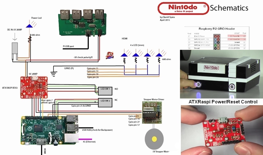
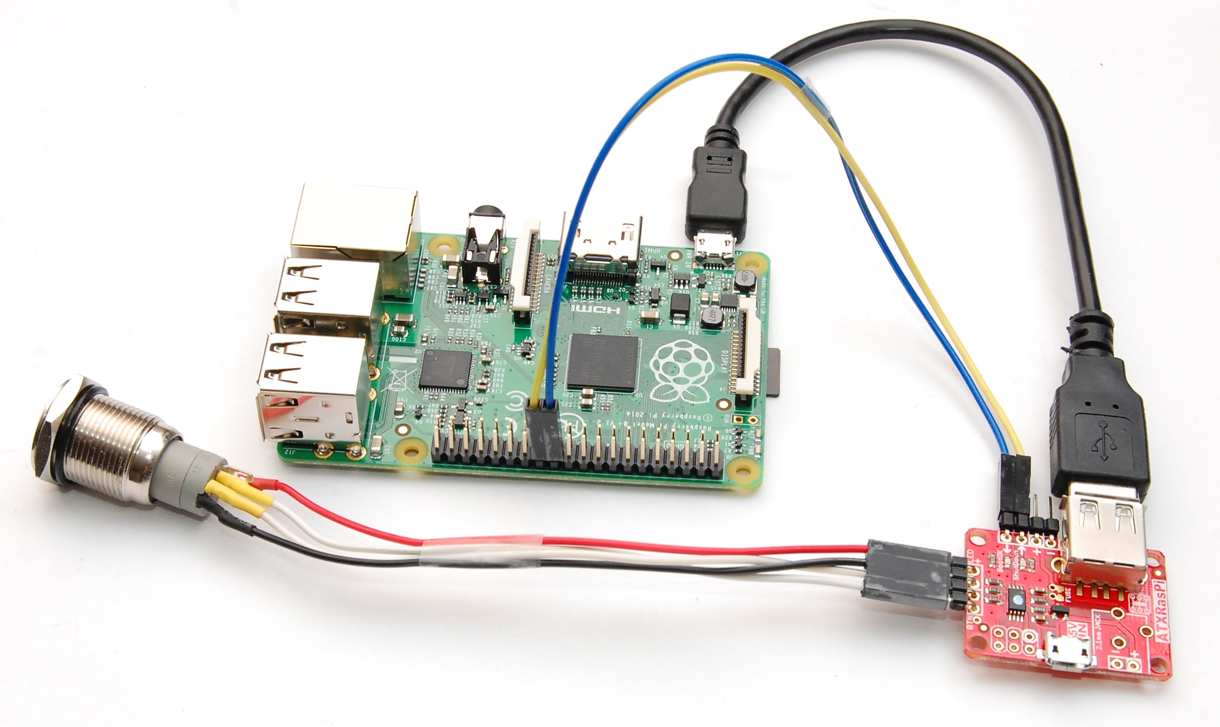
If you want to automatically power off your Pi when you run the shutdown command (ex. shutdown menu in xbmc), this can be done pretty easily through a small addition to the ATXRaspi circuit. Basically we need to tell ATXRaspi to issue a shutdown, from software rather than from the button press. We can simulate the power button press usgin a NPN transistor from any Pi GPIO. Below is an illustration how this can be done with GPIO10:Please note: this only works for momentary button operation. It will not work in latching/slide switch mode.

Here’s a sample script that should run when you want to shutdown or reboot your Pi, save this script as /usr/bin/local/softshutdown.sh:

#!/bin/bash
BUTTON=10

#setup GPIO 10 as output and set to HIGH
echo "$BUTTON" > /sys/class/gpio/export;
echo "out" > /sys/class/gpio/gpio$BUTTON/direction
echo "1" > /sys/class/gpio/gpio$BUTTON/value

#keep GPIO 10 high for at least 4 seconds for shutdown, 1s for reboot (same as pressing ATXRaspi button)
SLEEP=${1:-4} #default to 4 seconds if no delay value was passed

re='^[0-9\.]+$'
if ! [[ $SLEEP =~ $re ]] ; then
   echo "error: sleep time not a number" >&2; exit 1
fi

echo "ATXRaspi button press for: $SLEEP seconds..."
/bin/sleep $SLEEP

#restore GPIO 10
echo "0" > /sys/class/gpio/gpio$BUTTON/value

Make it executable with sudo chmod +x softshutdown.sh, then the permissions on this script should be the following:

pi@raspberrypi3:/usr/local/bin $ ls -la
-rwxr-xr-x  1 root staff  580 Dec 29 17:59 softshutdown.sh

Since /usr/local/bin is in your PATH variable (check with printenv command) you can now execute/edit the softshutdown.sh from anywhere). Also note this script takes a single decimal/numeric variable which represents the delay of the “button press”, if no value is given then the default is 4 (seconds), and this simulates a shutdown. For a reboot, pass a value of 1: softshutdown.sh 1.

Let’s do something cool and create aliases to execute shutdown and reboot in raspbian, run the following (use your own custom alias if you’d like):

$ printf "%s\n" "alias atxshutdown='sudo shutdown.sh'" >> ~/.bashrc
$ printf "%s\n" "alias atxreboot='sudo shutdown.sh 1'" >> ~/.bashrc
$ source ~/.bashrc

This adds permanent aliases to your .bashrc file and activates them. Now you can run these commands from anywhere:

  • atxreboot to trigger a reboot – ATXRaspi status LED will blink and wait for Pi to reboot
  • atxshutdown to trigger a shutdown – ATXRaspi button status LED pulses until Pi is halted, then it cuts power off as usual!

Using with XBMC

For XBMC you can do it somewhat simpler since there is a shutdown menu which invokes a shutdown command that can be replaced with invoking a custom script. You can use the following equivalent script, save it as /home/pi/softshutdown.sh:

#!/bin/bash
sudo gpio -g mode 10 out;
sudo gpio -g write 10 1;
sleep 4;
sudo gpio -g write 10 0

Next modify this file: /opt/xbmc-bcm/xbmc-bin/share/xbmc/addons/skin.confluence/720p/DialogButtonMenu.xml, and in the “Shutdown description” section replace XBMC.Powerdown() with System.Exec(“/home/pi/softshutdown.sh”). You may need a reboot for this to take effect. Now when you shutdown XBMC, the transistor will simulate shutting down from ATXRaspi, and will power off your Pi as usual !

This was also posted as a guide here, and was inspired from this forum thread, thanks to all contributors!
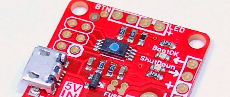
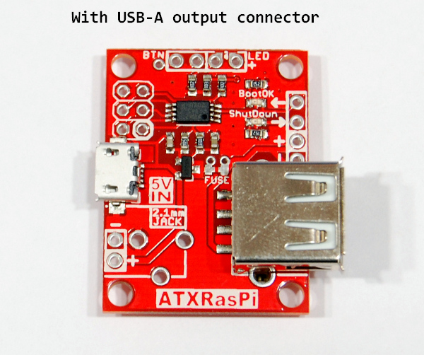
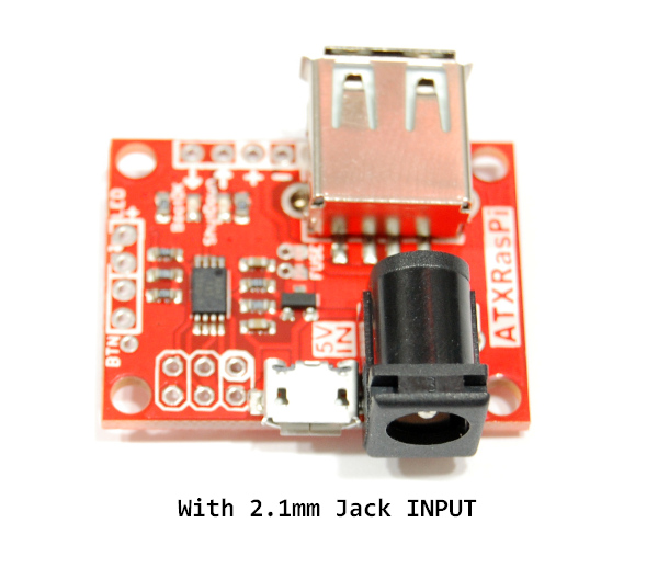
ATXRaspi+fan+LCD load tests

This is a summary of some load tests I did on the ATXRaspi. People often ask: How much load can the ATXRaspi support?

I used the following hardware, and I wanted to see how much current the official DSI display will draw in addition to the Pi.

  • RaspberryPi3, Model B v1.2 (Raspbian Jessie, no overclocking)
  • small 0.2A fan that is a popular accessory and often used with the Pi
  • the official Pi Foundation DSI Display

I threw in the 0.2A fan just to put an extra strain on the power supplies. Here are the 3 supplies I tried, and while all could run this setup without instability issues, the Under Voltage Warning (UVW) would come up at times, especially on the Apple supply which would show it constantly and the 5V GPIO rail would stay at ~4.8V. The best was the CanaKit 5V/2.5A, with this supply the UVW would only appear intermittently during boot, and would settle at ~5.05V after boot. So the CanaKit supply was used for the following tests.

The trusty Fluke 87V was used to measure the LCD amps and the GPIO 5V rail during boot to a console. Here is the setup and average mAmps used by the LCD at boot time:

Here are the peak recorded mAmps used by the LCD, note that this MAX was registered during (re)booting. The Pi LCD settles to ~450mA after booting is complete.

And here are the measured Volts with the CanaKit 5v/2.5A supply, again note that the 4.93V was recording during booting, after which it settles to ~5.0V:

A basic scope roll measurement was done to look at any MIN/MAX peaks and overall 5V rail behavior, note how the voltage starts at ~5.2V then the LCD starts up and voltage goes to a stable ~5V where it settles during/after boot, otherwise no odd dips or spikes:

Here is the Under Voltage Warning that might show up. With the CanaKit supply this showed intermittently only during boot. With the other supplies it was more apparent and with the Apple supply it was constantly showing all the time. Without the LCD this warning would never show with the CanaKit supply, but would show with the others.

Even so, the Pi behaved normally with all these supplies and there was no observed instability.

According to official Pi release notes, the UVW shows when the 5V voltage rail drops below 4.65V. In the tests above this condition could not be recorded with any of the supplies tested, either with an oscilloscope (roll 128ksps) or with the Fluke87V in Voltage Peak Detect Mode (1ksps+). Even with the worst performer (Apple supply) the MIN peak  was around 4.7V and settled around 4.85V after boot.

The conclusion is that ATXRaspi supports quite a hefty load, but to avoid the Under Voltage Warning you really need a very good supply, at least 2.5A.

This content was also posted under the official ATXRaspi Guide.

Featured project: Nin10do game console

Retro gaming enthusiast Daniel Spies has put together a wonderful RetroPi game console (Now on LifeHacker Australia!) that can emulate popular consoles like NES, MEGADRIVE, PLAYSTATION and has shared his project for posterity. He designed a 3D printed case in Autodesk123D with a stepper motor operated front cover, indicator LEDs, ATXRaspi for power and reset control, and of course the RetroPi for the RaspberryPi OS. It’s one of the most polished projects I’ve seen from an amateur maker/hacker and it includes a series of very detailed youtube walkthroughs of the entire hardware+software setup. Here’s the first part of the video series, where he’s building the wiring/electronics and fitting it into the 3D printed case:

Here are some snapshots I captured that highlight some of the details of the project:

The rest of the videos and more details of the build can be found at his Nin10do Hackaday.io project page. It was a pleasure watching him build this cool project so be sure to check it out as well!

New ATXRaspi reboot function

ATXRaspi will start to ship with a new reboot function in addition to the shutdown function it had since inception. This was implemented because it was a cool feature to have and also suggested by several ATXRaspi users. See video above for a full overview and setup guide for ATXRaspi.

This will be in revision R2.6 boards but until that is released, revision 2.5 boards that have the reboot function will have a blue dot on the main chip (see photo above). The differences are the following:

  • to reboot: hold the button pressed for at least 0.5s and and less than 2s. The button backlight will dim once the reset threshold is met. Release the button and ATXRaspi will emit a 500ms HIGH pulse on the SHUTDOWN signal pin. It will then blink the button backlight for up to 1 minute while waiting for the Pi to reboot and the BOOTOK signal to be restored by the shutdowncheck script (to become HIGH again).
  • to shutdown – nothing changes: hold the button at least 2s. As before, the button backlight pulses slowly while the Pi shuts down. Once the shutdown is complete and BOOTOK signal goes LOW, ATXRaspi waits a few more seconds and cuts power off to the Pi.

The shutdownchecksetup.sh install script was updated to support the reboot function and is backward compatible with all previous ATXRaspi revisions. Here’s a photo of the required wiring to the GPIO and an example wiring of the chrome button offered at the LowPowerLab shop:

Making a custom RaspberryPi case

Bulk made enclosures are useful when you just want basic underwear on your Pi but what if you need to put something else in there and it won’t fit? I’ve built a Pi enclosure for my home automation gateway before but it was just 3 layers of acrylic to hold everything together, turned out nice. In this post I will show another example enclosure for a Pi gateway.

I am finishing up a separate project where I needed to put a Pi gateway in an elegant enclosure along with an ATXRaspi+power button, and a Moteino. This guide can be used as a guide to build a RaspberryPi+ATXRaspi+Moteino setup that can all live together in a nice box to serve as an internet gateway to your Moteino or other wireless Internet Of Things network.

I will show you how I made the case and the steps I took to avoid wasting material while adjusting the cutouts. I will include the corel and DXF files that I used to lasercut the case. I have a 60W laser cutter imported from china, and that makes for a very nice prototyping tool to cut and engrave the boxes, but they are becoming widely available at hacker spaces and workshops all around.

First let’s see what components go in the box: Continue reading

PiGateway upgraded to MightyBoost

ATXRaspi is great for enhancing your Pi with a power button that will gracefully shut down your Pi without the need to login to do that. I’ve been running my Pi like that for at least a year. But I felt like I needed something new, more powerful.

Enter MightyBoost – a multi purpose PSU that can supply the power a Pi needs, and also be controllable by a Moteino (including wirelessly controllable if needed) such that it would duplicate the functionality of ATXRaspi. And most importantly to be able to run it on battery backup in case power is lost, to avoid SD card corruption and downtime. Also it can monitor the battery (via Moteino A7) and shutdown the Pi in time before the battery runs out, as a last resort. Without a Moteino it can be used as a general purpose 5V boost-from-lipo power supply, that can also charge your tablet/iPhone/droid/etc.

I have now upgraded my Pi gateway to using MightyBoost. I had to lasercut a new mid layer for my existing Pi Gateway lasercut case. I have posted the changes (corel and DXF files) in the github repo so you can customize &/or lasercut your own if you’d like. As usual, I like to cut the new template in cardboard and do a fitting test, measure any adjustments, re-cut if needed, then finally when it’s perfect cut it in the more expensive translucent acrylic. Continue reading

ATXRaspi code update

Hello ATXRaspi users!
The previous version of the script was running OK, but there was an obscure side effect which I had overlooked. The script was invoking “sudo sleep” in between checks of the shutdown signal from ATXRaspi, and this in turn was generating new entries in /etc/log/auth.log every time, yikes! Thanks to Chris L. for pointing this out. The problem with that is the Pi’s that run from SD cards will have continuous activity to the file system and onto the disk and hence increase the risk of data corruption after very many disk accesses to the flash media. As Chris noticed, this also produces over 300MB of log per week, which gets archive into about 7MB (gzipped), not terrible in terms of disk space usage but still highly undesirable. I have changed the script to remove this side effect and reflected the install changes on the ATXRaspi page.

UPDATE: A big improvement is also the change to a single setup script that needs to be run to install the shutdown script. No more dependency on WiringPi. Just type 2 commands and reboot your Pi and you’re done!

Another notable change was that I moved the install location from /home/pi directory to the /etc directory where system code should generally reside.

I encourage all existing ATXRaspi users to upgrade to the new script. Since this is the same script that would be used by MightyBoost+bare Moteino that emulates ATXRaspi behavior, they should use the same new script. As always, please feel free to report any issues and improvements, the forum is a good place to do so.

ATXRaspi 2.1 released

ATXRaspi now comes in red soldermask!
Other than that a few things were moved around a little to make more space for the 2.1mm barrel input jack which previously could only be soldered without the uUSB connector.
The LEDs have been rearranged to match the “BootOK” and “Shutdown” silkscreen markings – each is now next to the relevant LED for less confusion.
Also the button is now taking only about 3 seconds to hold until a shutdown is triggered, and a total of about 7 seconds for an unconditional power cutoff.


Introducing ATXRaspi R2

A new revision of ATXRaspi was in the works for a long time. Based on user input and other suggestions I came up with what I think is a better incarnation of it. Special thanks to Mike from mikesmicromania for all the valuable feedback and suggestions on this new revision!

ATXRaspi_R2

Among other features:

  • all SMD components yield a more efficient layout and a leaner profile
  • More input options: microUSB, 0.1″ header, 2.1mm barrel jack
  • More output options: 0.1″ header, USB type A (female)
  • poly fuse footprint allows you to add your fuse of choice directly on the ATXRaspi (through hole or SMD)
  • onboard SMD LEDs help visualize signals between ATXRaspi and RaspberryPi
  • extra output power header pins (2x5V, 3xGND)
  • backwards compatible

This version is making a huge difference in manufacturing, as I assemble everything by hand. R1 was difficult and time consuming to assemble. While R1 worked great, the relay would be prone to voltage spikes and drops depending on the quality of the input supply, hence causing glitches and requiring multiple button presses to turn power on (an effect that was reduced by wrapping the output power wire around a ferrite bead). This new design uses a mosfet which drops only 10-15mV of power and these effects should not be manifested any more.

Just for fun, here’s the stencil I produced for ATXRaspi R2 with my DIY stencil method, and the results after paste application:

Please use the forum to submit more feedback and suggestions which are always welcome!