
The source code for SwitchMote is finally “done”. As always, consider this a beta release at best, you should always check the github repository for any updates. There are 2 parts to configuring and programming a SwitchMote.
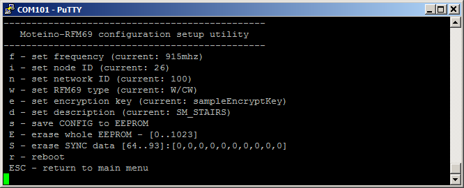
SwitchMoteConfig sketch, which needs to be loaded and used once, after assembly and before SwitchMote installation. This sketch is meant to help setup the essential parameters of the Moteino in the SwitchMote such as frequency, node and network IDs, RFM69 type (W or HW), encryption key, description, and some other utilities that may be extended in the future. All these parameters are then stored to EEPROM and will not be dependent on hardcoded values in your sketch.
This is especially useful when you have some nodes with RFM69W Moteinos and some with RFM69HW. It’s hard to keep track of all the transceivers settings. Additional settings could be added, like power level, bitrate, etc. Keeping the configuration with each node is most efficient in applications like SwitchMote. Setup once and forget!
SwitchMote sketch is the permanent sketch that will get loaded on your SwitchMotes. Note that this sketch will read the EEPROM configuration that was setup with the SwitchMoteConfig sketch mentioned above. This sketch does several things.
- keeps track of which buttons were pressed, and manages the modes of operation
- any button can be in ON or OFF mode – reflected in GREEN or RED led status
- listens for BTNx:y tokens, to put button x in mode y, x={0,1,2}, y={0,1}
- listens for SSR:y tokens, to turn the SSR on or off and the associated button in that same state (reflected by the LEDs)
- if the button associated with the relay (SSR) is pressed then the SSR is turned ON or OFF depending on the mode that button transitions to
- if a button is held pressed for at least 3 seconds (configurable) it enters SYNC mode, explained below
- if a button has SYNC data it will notify the remote SwitchMotes to virtually “press a button”, and transition that button to the mode specified in the SYNC data
- if any button is held pressed for at least 6 seconds (configurable) it erases the internal SYNC data in EEPROM. This could be modified such that only the SYNC data associated with the pressed button is erased, not the entire SYNC data
- notifies the gateway, if any present, that a button was pressed
Note that SwitchMotes loaded with this sketch will work independently and with each other without the need for a network gateway or coordinator. A gateway is by default notified but the feature can be removed if not desired.
Also note that a SwitchMote can work without a relay, in which case only the neutral wire N and a hot wire to either one of S1/S2 is needed. In this case the SwitchMote can just act as a controller for other SwitchMotes or be customized to send other commands to other Moteinos. For instance you could open/close your garage (with GarageMote). The sky is the limit of what you can do.
Further details of the SYNC feature and how to use it are documented on the SYNC mode section of the SwitchMote page. Please refer to that page for any updates and latest information on SwitchMote.
Happy switching & sync-ing!
P.S. This code was released for RFM69 transceivers only because of huge growing interest in these line of transceivers and diminishing interest in RFM12B. You are welcome to port this to a RFM12B implementation as long as you keep within the boundaries of the CC-BY-NC-SA license.
I only had time for a quick look at the SwitchMote code, I liked what I saw. I like the syncing and other systems you came up with for SwitchMote. Looking forward to digging into the code to see how you did it.
FYI, slight mistake in the blog post – the “SwitchMote sketch” link is pointing to the url for: SwitchMoteConfig.ino
Like how you’ve done the config utility so values don’t need to be hard coded in the main sketch – nifty idea!
Pingback: Open Source SwitchMote Promises Easy Home Automation
I like the design and I think the whole concept is great. I am working on a similar project with a touch screen and lcd. But haven’t decided on how to power my board. I like the design with SR086. But this won’t do for my project. I also saw on your circuit diagram that you have a mistake? Power from the VREG on SR086 says you have 5V, but quick search on SR datasheet shows that it is 3.3V. I am right or did I just miss something?
It’s 087 which is 5V output on VREG, the eagle part may have 086 on it.
Hi
I noticed on the HaD post, you were talking about that an isolated power supply would be required for UL certification? Why? Regular wall dimmers don’t have isolated power supplies, regular switches don’t have isolated power supplies, and probably most cheap line powered devices that have low current requirements to do a few logic things don’t. Have you ever looked at Microchip app note AN954? ww1.microchip.com/downloads/en/AppNotes/00954A.pdf They even show some designs with “UL considerations designed in”, but of course warn that that’s not enough to necessarily meet the UL test yourself.
I ordered the parts to build the non-isolated capacitive version they mention with just the cap and zener and couple other parts a long time ago, but haven’t actully got around to doing it yet. I did measure the average power consumption of a RFM12B staying in RX mode continuously, and bursting TX, and an Atmega with some reasonable power saving measures in the code (consult the datasheet – not sure that all of that is available through the arduino libraries or not, but I just write bare metal C code), and it was easy to build that power supply with enough current capacity to do exactly what you’re doing (line powered), but with only a couple passives.
I also commented on your rfm69 library when you first posted it (about the weird discrete interrupts), and I did get mine written finally, and you really do only need one interrupt line. I was also successful in setting all the parameters on the RF69 the same as the RF12, and they are completely inter-operable. Now if I ever got around to spinning some new PCB versions that had the RF69 footprint instead of the RF12 footprint, I could put some of the 50 of them I bought into use, besides the 2 I have in breadboards for testing!
The issue with non isolated is that people don’t tend to trust them very much, with good reason. And I agree my R1 of the SwithcMotePSU is not UL compliant, even though it is functional and does the job. Work is being put towards a new version that is a lot more compliant. Isolation does a lot for your protection.
If you ever publish your RFM12B-RFM69 solution I’m sure a lot of people that have lots of RFM12Bs woudld be interested.
Oh, and from reading a comment above, maybe another idea for you (I haven’t had a chance to see how you implemented your address setting – maybe you came up with a similar idea already). I wanted a way to be able to program a bunch of units without having to set the addresses manually. What I do is send a “set address” command with a new address to a broadcast address so all modules get it, go into ‘set address’ mode (flash some LEDs a certain way on the unit to give visual indication) then wait for the user to press a button on the remote unit to confirm, and only the module where the button is pressed sets the address – the rest timeout and ignore the command. That way you can program all units from the get go without setting the individual addresses, and just set them once they’re wired up and in circuit already.
If you go that far as to program the address remotely maybe it’s worth to take another step and actually have it completely wireless, the main reason being that not all nodes might have a “change ID” dedicated button. For that you’d need to know the target ID.