MoteinoLeo: new LowPowerLab family member

MoteinoLeo_R1_withFlash

Update: MoteinoLeo is now discontinued and no longer available for sale.


The difference between MoteinoLeo and the regular Moteino is pretty obvious – it’s got built in USB. It’s conceptually an Arduino Leonardo clone, with an RFM12B transceiver solderable on the bottom, with a few minor changes and some added features. It runs at 16Mhz, 3.3v, has an optional FLASH footprint for data logging (wireless programming on Leo is not yet achieved, perhaps in the future if a custom bootloader will permit). There’s also a 750mA PTC fuse to protect the USB against shorts or over current.

Design files are on the MoteinoLeo Github repository.

Here’s a pinout diagram:

MoteinoLeo_PINOUT

Compared to Moteino:

MoteinoLeo_top_comparedMoteinoLeo_bottom_compared_small

Schematic:

schematic_R1

Forum now open

I added a forum for open discussion and support at http://lowpowerlab.com/forum

This was suggested and it makes sense because all the support email I get is mounting and I find myself repeating a lot of answers to common support issues.

So please use the forum if you have an issue with LowPowerLab projects or products. I will try my best to respond in a timely manner.

Also please share your projects using Moteino or any other experience you think might be relevant.

FTDI adapter now available

UPDATE: Eagle schematic and layout are in their github repo.
There is now also a Moteino-USB version which includes the FTDI adapter and the Moteino all in one at a combined lower price.

Some people have been asking for FTDI adapters for programming Moteinos to avoid having to buy them from another store and hence pay shipping/handling twice. So I created one. It’s actually based on the Adafruit FTDI-friend which was a very good design. Here are the features:

  • 5V power level (default) – adjustable to 3V
  • 3V logic level (default) – adjustable to 5V
  • pin 6 is RTS (default) – adjustable to DTR
  • RX/TX LEDs
  • The pinout is standard [ GND – CTS – VCC – TX – RX – RTS ] and will work with any Arduino clone that has this as a programming interface.
  • compact layout

The underside of the board contains some jumpers that are shorted for the default settings mentioned above (5V power level, 3V logic level, pin6 = RTS) – these are standard settings that come with the FTDI cables and should work in most instances. Hackers may want to switch these settings – for this the default shorts need to be cut with a razor blade and the other jumper needs to be shorted by soldering the jumper pads together.

I’m working on sourcing some USB cables to go with these soon. Here are more images and the schematic:

DSC_0640DSC_0643_logo
DSC_0641Schematic


Wireless programming update

The initial code commit for wireless programming was a little sluggish and the performance wasn’t very good. I had to add delays to make sure everything was synch-ed and the protocol was working. The result was a rather slow wireless upload of a new sketch, especially if it was a large sketch. But it worked…

Today I worked on improving the protocol and was able to cut down the over-the-air upload time by a factor of ~5. The gains are mostly from improved serial communication. This will still take about twice as long as normal sketch uploads by means of an FTDI adapter. For instance, a 9,8Kbyte sketch takes me about 11 seconds to upload directly to a Moteino using an FTDI cable; wirelessly programming that same sketch takes about 22 seconds. Not bad given how involved the whole handshaking protocol works. And much better than almost 1 minute with the old code. So I’m classifying this new release as a beta. More improvements or bug fixes might be added later, but it’s definitely a functional release. I’ve uploaded different sketches of around 10KB several times without a glitch.

The wireless sketches examples (gateway and node) and the python script are in their github repo. The SPIFlash library was also updated (the WirelessHEX part of it), so get latest before you try this.

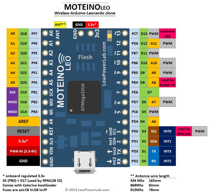
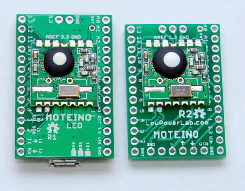
As mentioned before, the target node of the wireless programming protocol will need to have an SPI Flash chip attached (if they don’t have one already), and also run the DualOptiboot bootloader for this to work. Moteinos come with this bootloader (all orders since the other Wireless Programming post and code was released). If you have all these components right, any Arduino clone with an RFM12B transceiver and an SPI Flash chip of at least 32Kbytes of memory will do the job.

Just for fun, here’s how the end of a wireless upload looks like, notice there were 617 packets sent all the way from the PC (through the python script) to the attached Moteino (gateway), wirelessly to the remote Moteino (target node):

Transmission_end